When creating presentations of a product, it is often desirable to show it in the context of the component assembly. However, not all adjacent components have to be part of the analysis, but can only be used to illustrate the function and installation situation.
For this purpose, Abaqus Unified FEA offers a perfect tool, the so-called Display Body. This is one or more instance(s) in the assembly/model that are not included in the FE analysis, but are required for display in the results file. In this paper we want to introduce the definition of Display Bodies in Abaqus/CAE and the representation in the calculation result.
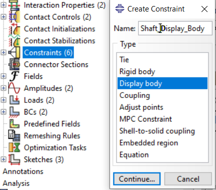
A display body is created via a constraint in the interaction module. Any number of instances can be used for one display body each, or all instances that are not part of the analysis can be combined into one instance and then defined as a display body.
In addition, it is possible to assign a boundary condition to a display body so that it follows the deformation/rotation of another component, such as the shaft of the hub in the example below.
A display body does not require a mesh (this is hardwired internally), but it can prove advantageous, especially when higher order element types are used, which can be used to achieve the best possible display in Abaqus/Viewer.
The use of display bodies has no influence on the computing time.
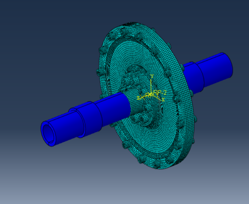
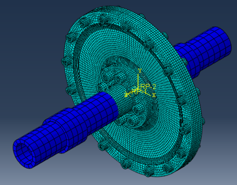
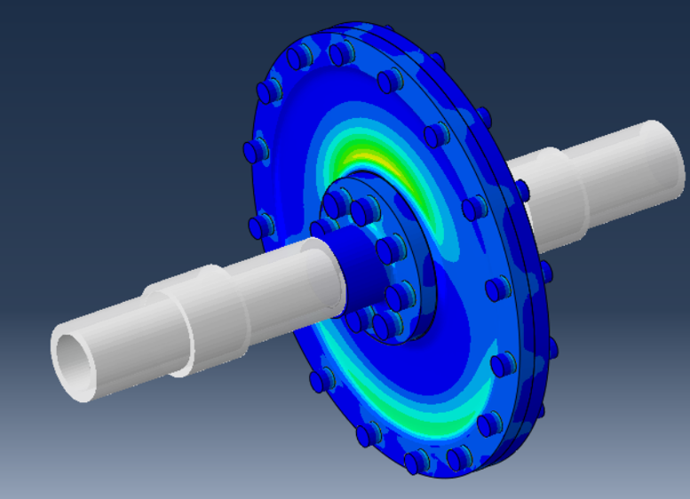
The example shows a double disk coupling connected by bolting with input and output shaft. The shafts are not part of the analysis, but they are shown as display bodies and follow the reference points of the couplings to the hubs of the disk clutch. Display Bodies are displayed in dark blue by default, but colors can be changed via the color dialog in Assembly mode.
A display body is defined in the assembly as a constraint.
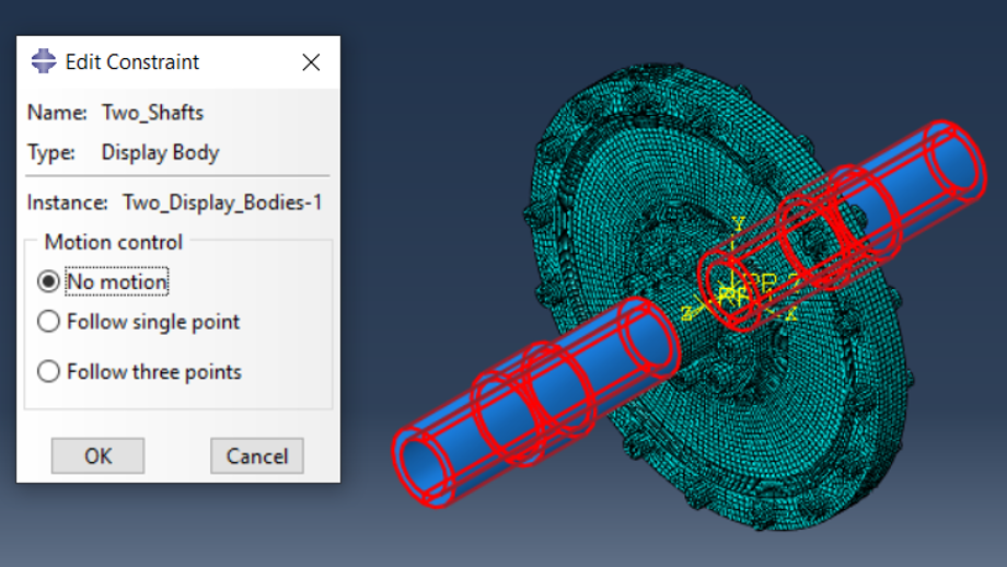
The following dialog is used to specify whether the display body should follow a movement. The control point can be a reference point or a plane of 3 points. A display body can only be defined for ONE instance at a time.
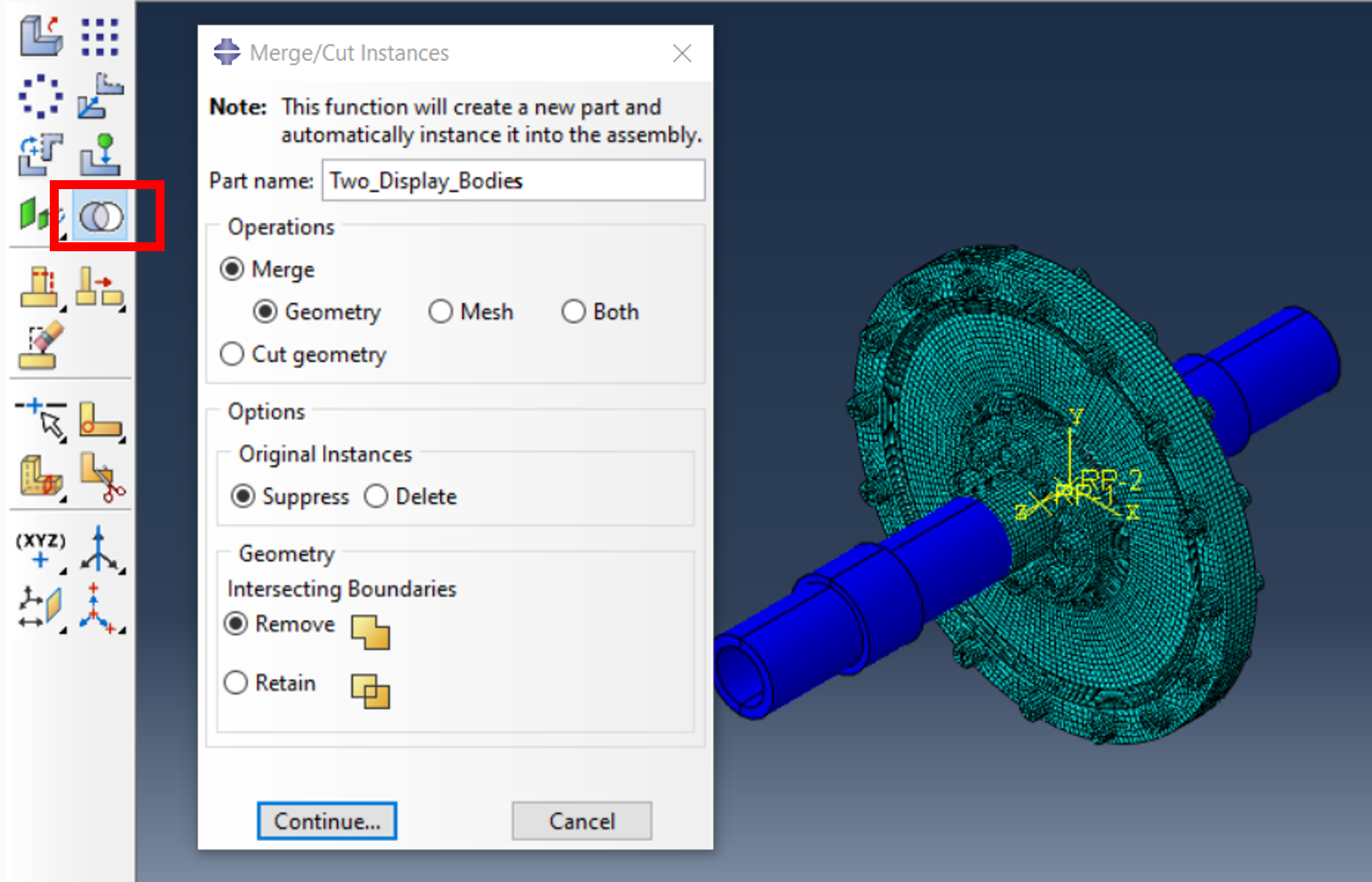
In the case, that multiple instances are to be defined as a display body, they can be combined into a single instance.
This is useful if they are not to perform independent movements. This is where the Merge/Cut Instances function is used.
After the two waves are combined into a single instance, the display body can be created.
For the highest display quality in Abaqus/Viewer, the display bodies should be meshed, preferably with higher order elements.
In this example, we use shell elements after deleting the cells and removing the inner faces.
The mesh density for higher order elements is of secondary importance, since the display quality in the viewer can be adjusted via the fineness level. The meshing is purely used for optical reasons.
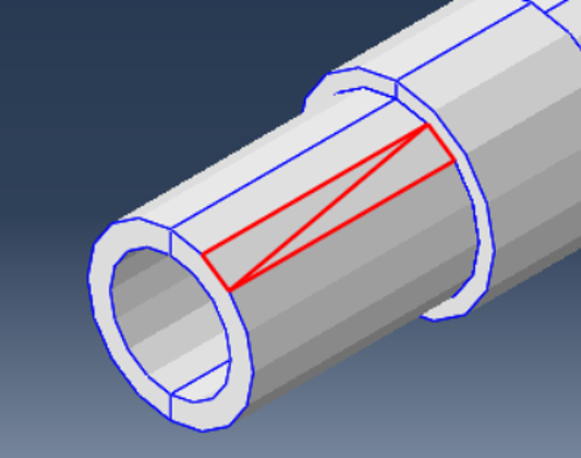
2 elements of a display body without meshing. The surfaces are divided into triangles, the size of which is not adjustable.
The quality of the display cannot be influenced even with a higher degree of fineness.
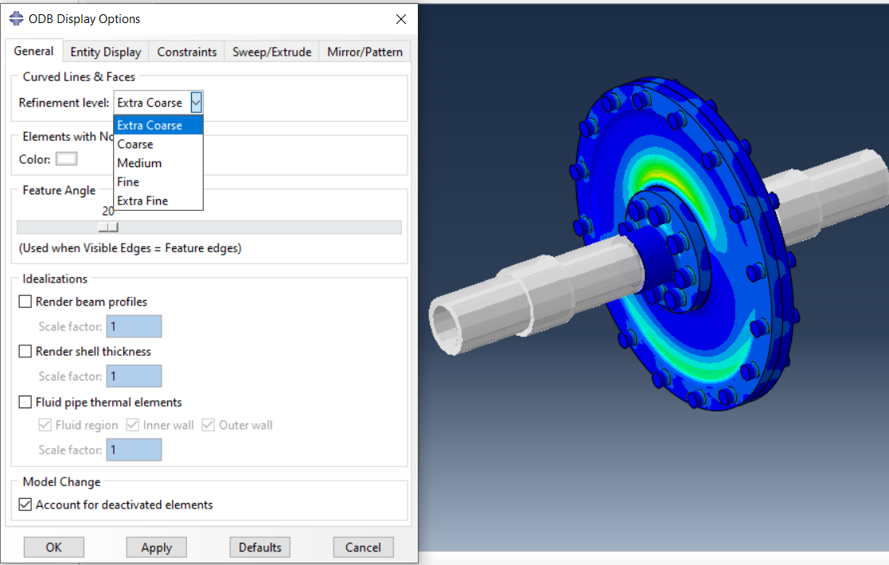
If the display body has been meshed, the quality of the graphic output can be set via the fineness level.
Because higher-order shell elements were used here, the quality can be adjusted as desired.
For higher order elements, the “Medium” setting is sufficient. If the fineness is set too high, the fine display can lead to the user not being able to follow the rotation in an animation when the wave rotates.
With the Display Body Options, the appearance of the display body can be set independently of the display of the results (transparency, border display, color, etc.).
Display Bodies can be used to integrate parts of an assembly that are only used for visualization into the calculation. When displaying the results in Abaqus/Viewer, there are many options for setting the desired quality.
The user is given all the freedom here and the additional effort is very low.
