The RSG Dialog Builder is a simple tool for creating plug-ins in Abaqus/CAE. This tool is delivered by default with every version. Here, the RSG Builder consists of two parts, the GUI and the executing script in the kernel of Abaqus/CAE. Such plugins can be used to automate the work process. We have already used RSG Builder in Abaqus/CAE: QuickStart Plugin with RSG Dialog Builder In this article we want to use RSG Builder to create standard components, in this case screws. Here we describe in detail the creation of the GUI and a script to run it. Screws are used to connect components together via contact and pretension. Especially for large assemblies, in which many components are connected by different bolt connections, such a plugin offers a valuable contribution to the efficient modeling of different bolt sizes. Even if this example seems elaborate at first glance: The creation of standard components is feasible even for users with little or no experience in scripting. The improvements to the script described in section 4 can also be implemented with little knowledge of Python.
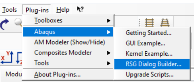
The RSG Dialog Builder is located in the menu item Abaqus Plugins, see the following image. RSG stands for “Really Simple GUI“.
The RSG Dialog Builder is divided into 2 windows:

The GUI window: The necessary parameters (variables) for the kernel module are defined here. There is a possibility to create pull-down menus, buttons, tables, etc. By activating “Show dialog in test mode”, you can see in real time how your GUI has been set up.

The kernel window: This is where the Python code is required for execution. As explained below, this Python code can be generated using the Macro Manager and, after a little revision, inserted.
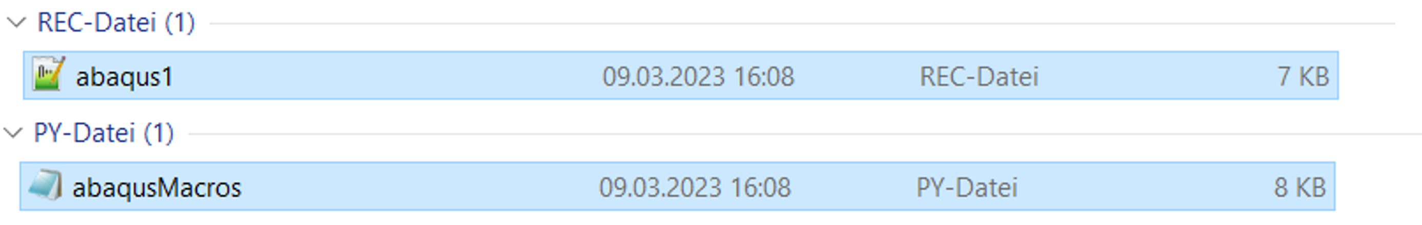
The procedure used here to create the Python script via the Macro Manager can also be used for other projects. Step 1: Starting the macro recorder Step 2: Creating the screw geometry, partitioning the screw and defining the material and section Step 3: Defining the element type and meshing the screw with a global element size Step 4: Closing the macro recorder The macro recorder creates two files with the names ABAQUS1.rec and AbaqusMacros.py. The content is accumulated, so it is recommended to delete an already existing file of this name. The file only contains the Python code required for the script.
Before creating the geometry, it is advisable to make a sketch of the screw and its parameters, see image below. This sketch can be further used in the PlugIn below. Likewise, a list of all parameters used should be created in advance. In this example they are:
DK = head diameter KH = head height LS = shank length LG = thread length DS = shank diameter Pname = name of the part Matname = name of the material Secname = name of the section Module = modulus of elasticity Dens = density of the material NUE= transverse contraction number msize = element size (% of DS) Standard values: DK~1.5*DS ; KH~DS

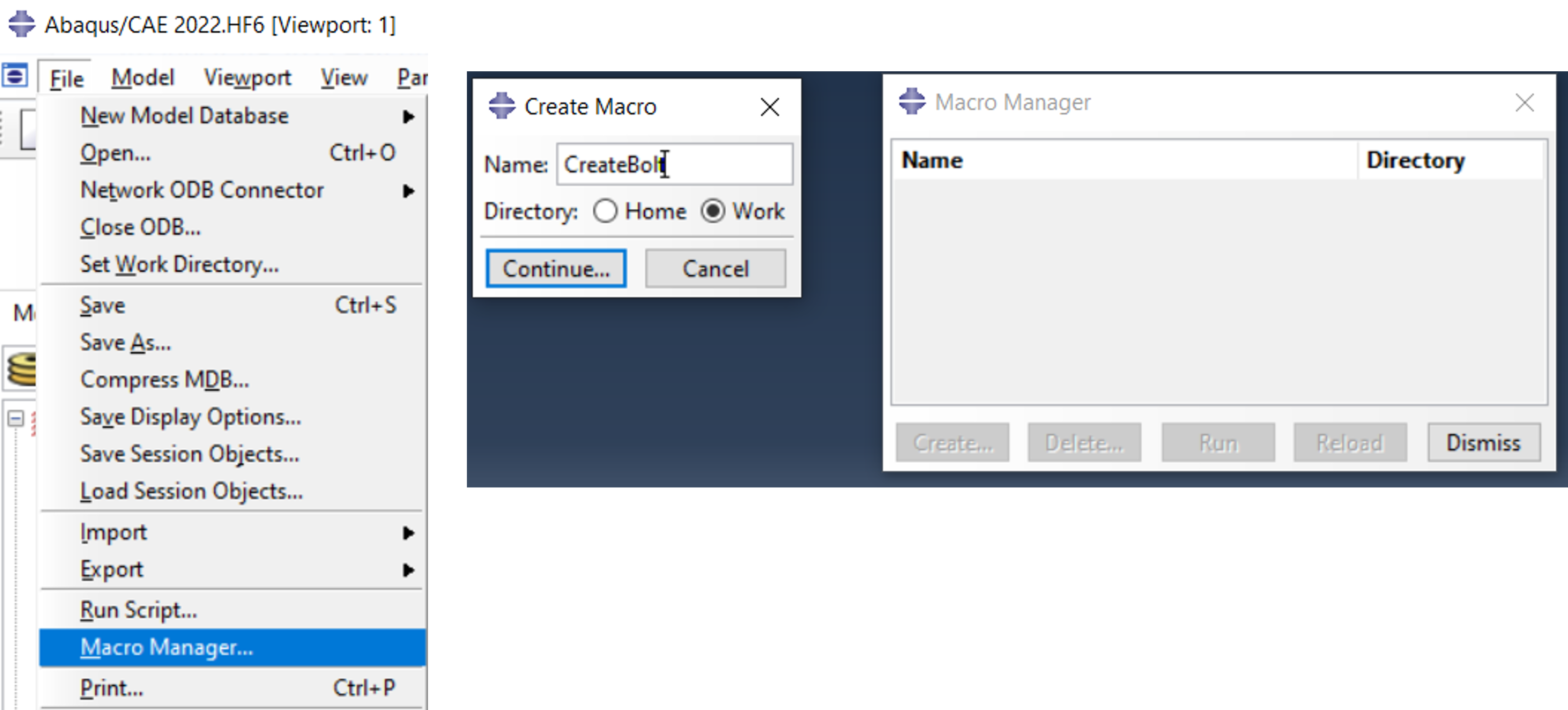
Step 1: Starting the macro recorder As shown in the picture below, start the Macro Manager via the Files tab. A new macro is generated there. It is recommended that you first save a new macro only in the working directory (Work).
Step 2: Creating the screw geometry and partitioning the screw When creating the geometry and datum planes, it is useful and helpful to use unique values, e.g. 7.777 for the parameter KH (head height of the screw). This way the value can be found quickly in the macro file and is then replaced by the corresponding parameter (see further down in the text). The part is called Bolt_Script. This name is freely selectable. Then a material and a section are defined. The section is assigned to the component.
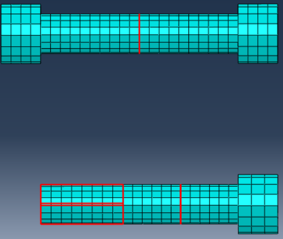
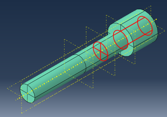
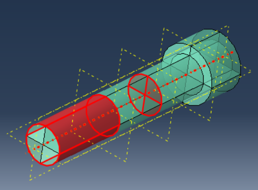
The partitioned component with the assigned section, the 5 datum levels and the “Bolt_Axis” axis, which is not absolutely necessary but is helpful for further scripts, is shown on the right. Further partitions are marked in red and will be explained in more detail later.
Step 3 : Definition of the element type (here C3D8) and meshing of the screw with a global element size. The element size is selected as 3,333. This value can therefore be easily identified in the script and replaced by a parameter.

Step 4 : Close the macro recorder.
Now the file abaqusMacros.py can be opened with the editor. Here the editor Notepad++ ([5]) is used for editing and processing.

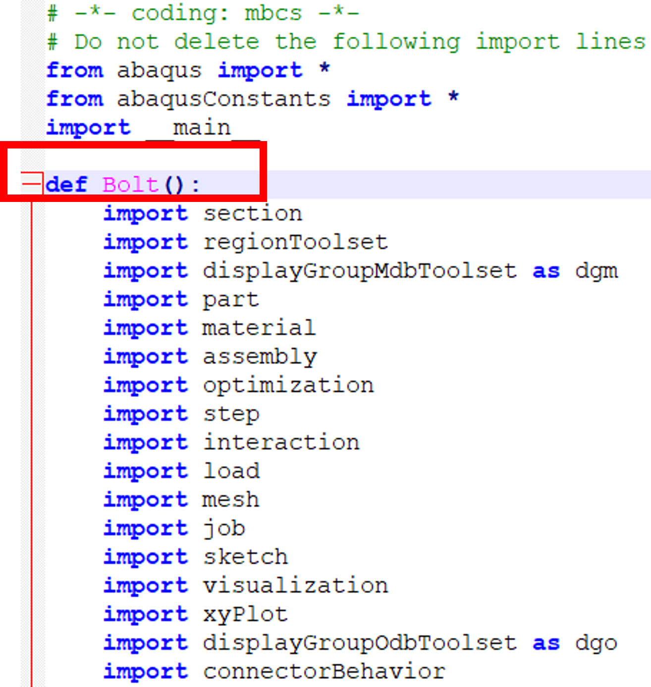
The macro is saved as a function (‘def’) in a Python script. The function does not yet contain any parameters and must now be filled. The import definitions are taken over, even if not all modules are needed. The name of the function may be changed.
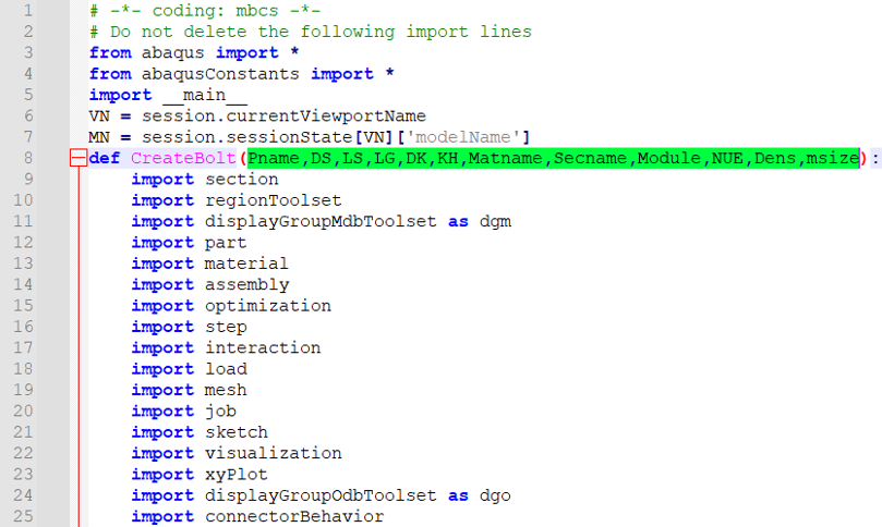
The function is now extended by the required parameters by entering the parameters as transfer values in the brackets after the function name. This is where the previously created list proves helpful. The order is arbitrary, but the list must be complete.
DK = head diameter KH = head height LS = shank length LG = thread length DS = shank diameter Pname = name of the part Matname = name of the material Secname = name of the section Module = modulus of elasticity Dens = density of the material NUE= transverse contraction number msize = element size (% of DS)
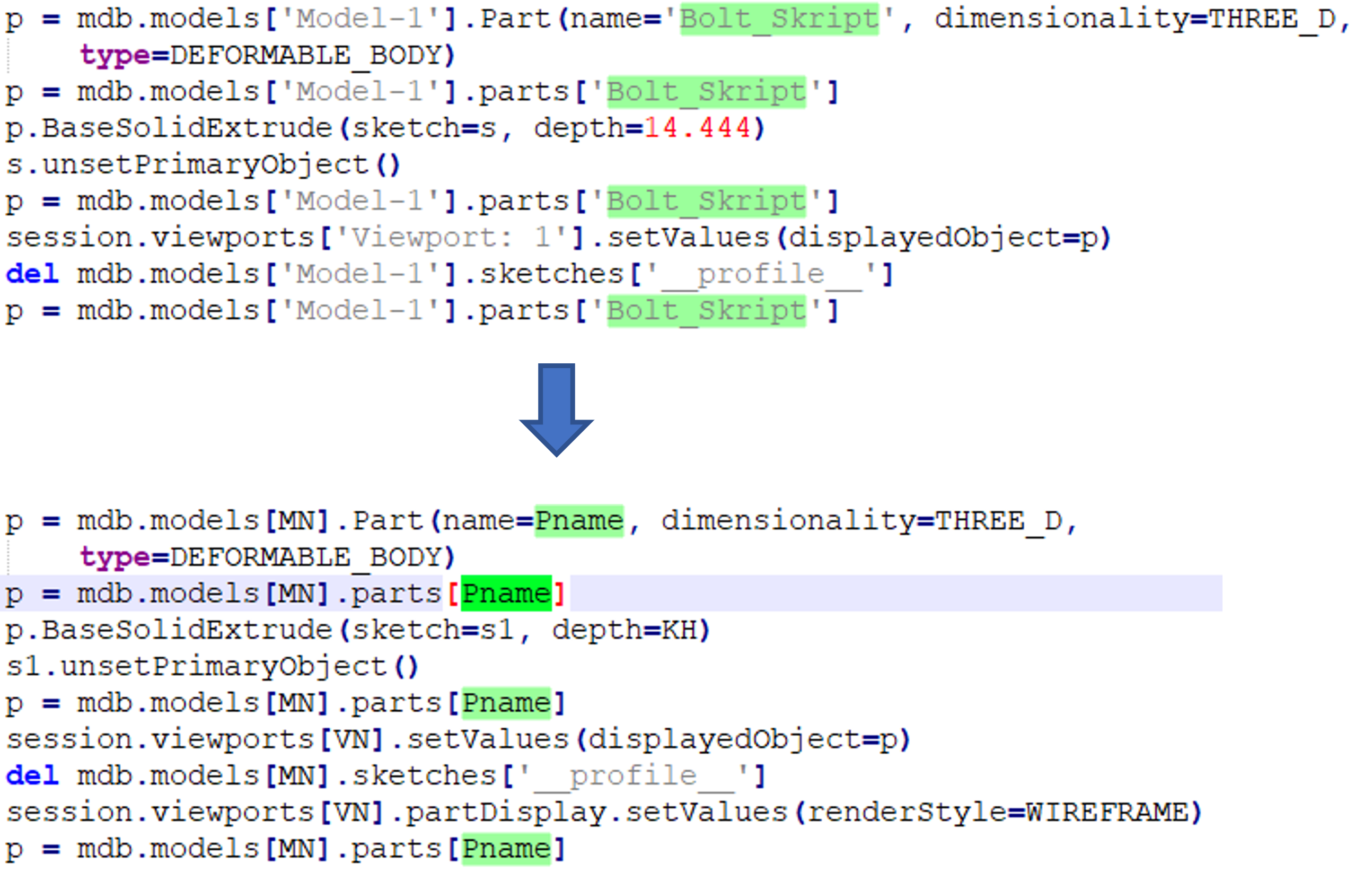
The placeholders VN and MN are generated. In the following, all entries of ‘Viewport: 1’ are replaced by VN and all entries of ‘Model-1’ are replaced by MN in the script. It is assumed that the part was created in Viewport 1 and the model was not renamed. Otherwise, the designations must be adapted accordingly.

All dimensions and names used when creating the part are now replaced by their parameters in the script file. This shows that it previously made sense to assign recognizable values to the dimensions.
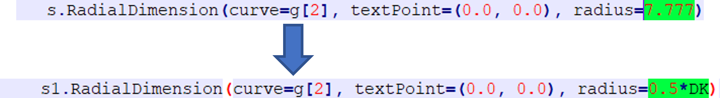
All 5 dimensions are replaced by the corresponding parameters (KH,DK,LS,LG,DS). The same applies to the date planes that were created with an offset from the xy plane (see image).

Finally, the remaining parameters used in the script are assigned, here the part Bolt_Skript is replaced by the parameter Pname (the quotation marks of Bolt_Skript must not be copied). Once all parameters in the script have been assigned, it is saved with the extension .py (here: Bolt_without_Nut.py) and can now be used in the RSG-Builder. It is recommended to use a powerful editor up to this point, as the editor in the kernel module only offers limited functions.
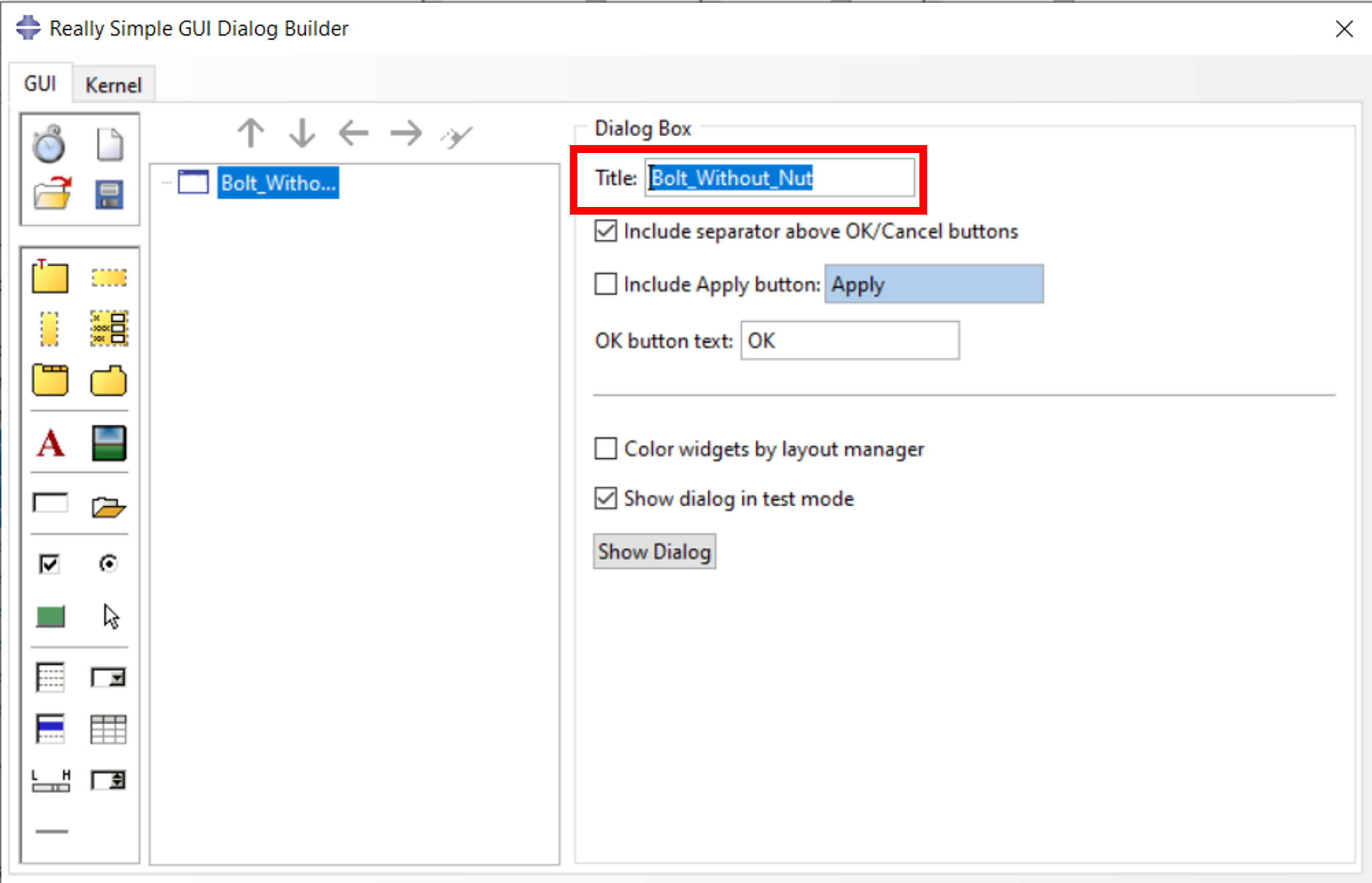
Now open the RSG Dialog Builder and assign a title first
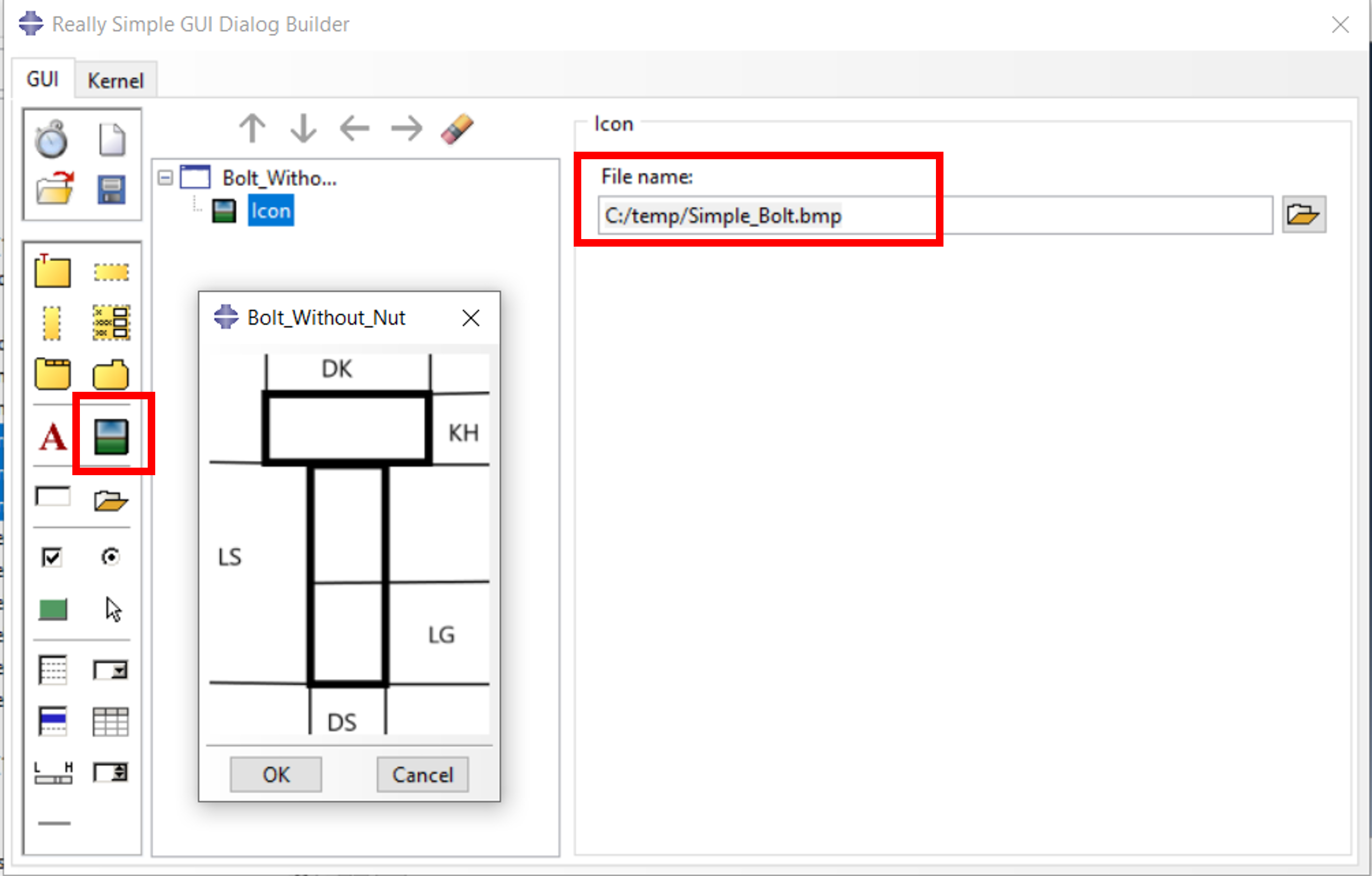
In this example, it makes sense to include the previously created sketch
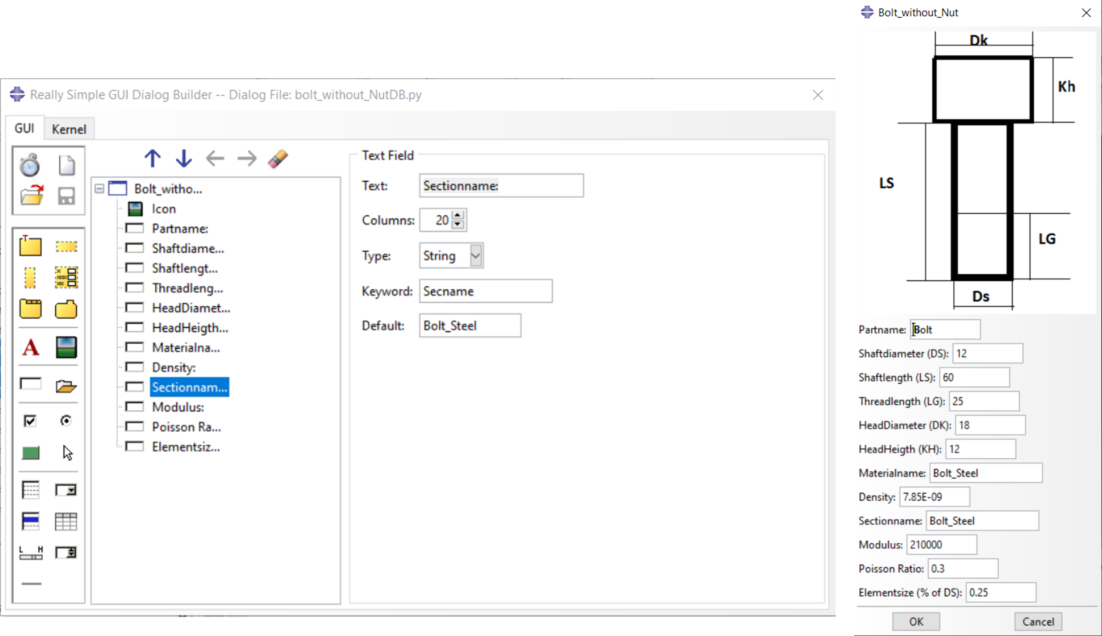
Now 12 text fields are created for the 12 parameters Text: Enter the text that describes the parameter in more detail here Type: A distinction is made between String (character string), Float (numerical value) and Integer (integer value) Keyword: Name of the parameter for the kernel Default: Preset value

The finished GUI on the right in the picture below.
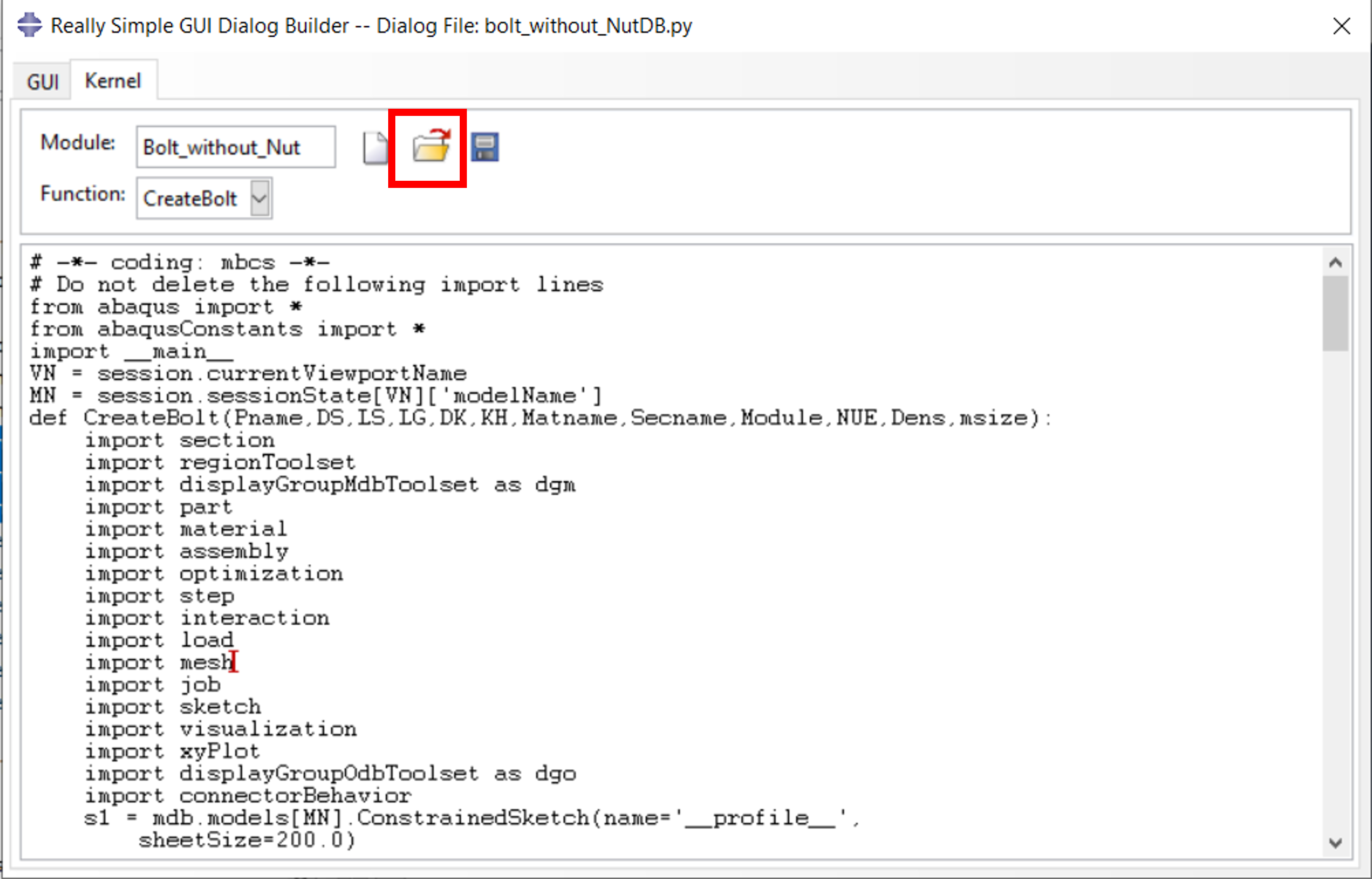
Loading the script: The script is loaded into the Abaqus/CAE kernel via the ‘Kernel’ tab and the ‘Open file’ icon. The script can also be edited further in this dialog.
The ‘Save file’ icon now saves the script under a name to be assigned, preferably in the working directory. If the script is to be loaded with every call, it is recommended to move the plugin from the working directory to the plugin directory of the installation afterwards. For Windows versions, this is e.g. : C:\Simulia\CAE\plugins23 Alternatively, a central plugin directory can also be used. This is defined via plugin_central_dir in the environment file, see [4]. The PlugIn should only be stored in one directory, because Abaqus/CAE searches numerous locations for PlugIns and in case a PlugIn is found multiple times, a warning is issued when CAE is started. Saving it as an RSG PlugIn ensures that it can be subsequently edited and modified again.

In this example, the ‘Bolt_without_Nut’ directory for the plugin contains the following files: bolt_without_Nut_plugin.py, bolt_without_NutDB.py, bolt_without_nut.py and Simple_Bolt.png. We simply copy the entire directory to C:\Simulia\CAE\plugins23. If we start Abaqus/CAE now, we can call the plugin (left in the picture below). Note that in the plugin the names for the new Part, a Material and a Section are agreed, in the image below center. A separate part name should be used for each screw. If the materials of different screws differ, new names should be defined for the material and the section. Otherwise, previous definitions will be overwritten without warning. The screw has now been created and meshed (bottom right in the image) and can now be imported into the assembly.

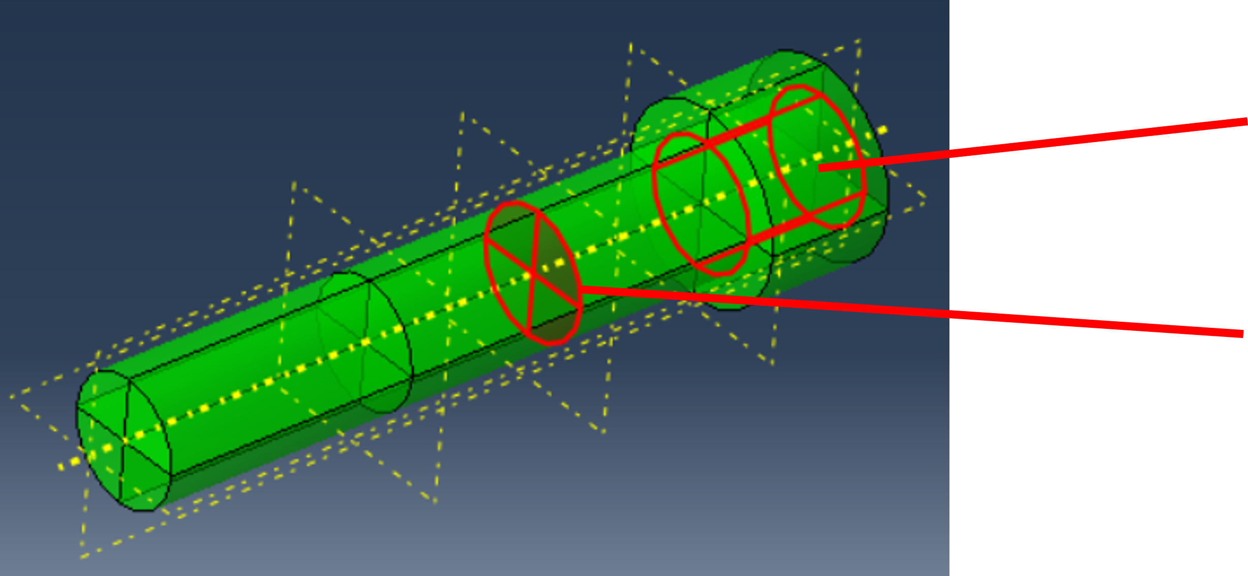
The screw created after calling up the plug-in. Shown in red are: Datum Bolt_Axis , surface BL_Surf for the bolt force and surface “Pname_+_Tie” for the connection of the threaded part to the corresponding component.
Once the plug-in has been successfully created, valuable tools are available to the user:
- Quick creation of any number of different screws
- Easy application of screw preload over predefined area without interactive instance selection
- Easy selection of surfaces for connection with the components of the assembly
Such a plug-in is indispensable, especially for very large assemblies. Even if this article seems complex, creating a plug-in with the RSG Builder is, with a little practice, a powerful and simple means of efficiently reducing the effort required for recurring processes.
It is not guaranteed that the plug-in will always work across all versions. This is because the partitions shown here in red were created with lines selected interactively. These lines appear in the script as a sequence of numbered lines whose numbering is not necessarily identical from version to version. The same applies to the inner surfaces for the bolt preload force and the surfaces of the threaded part. In this chapter, a more general scripting procedure is presented, which is intended to prevent the occurrence of such potential problems.
Partition of the screw head
Surfaces for bolt force
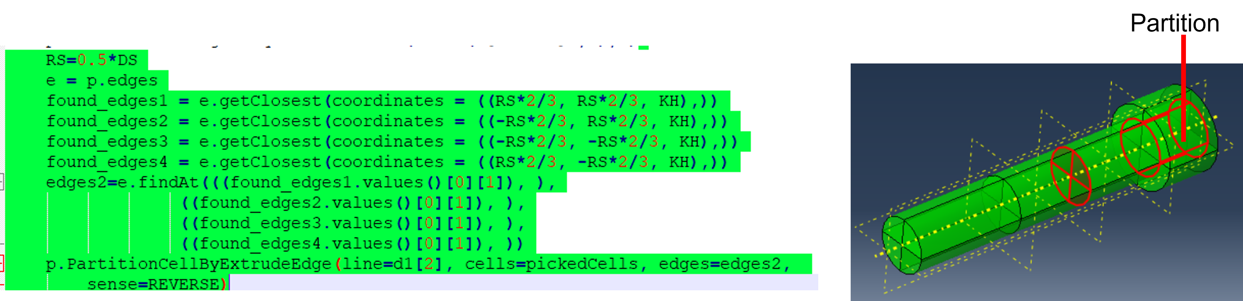
In the above procedure with the Macro Recorder, the lines (edges) are selected directly and the script uses the IDs of these edges, as shown in the image below.

We replace this definition with a search for the 4 arcs required for the partition. We benefit from the fact that we build up the screw ourselves within the part and thus the values are available for the search. The script block shown in the image below replaces the code from the macro recorder.
By using the Macro Recorder, IDs are used for the surfaces, see image below. These IDs could change.

We now use a script to find the 4 quarter circles required for the bolt force. The following block replaces the code from the macro recorder.

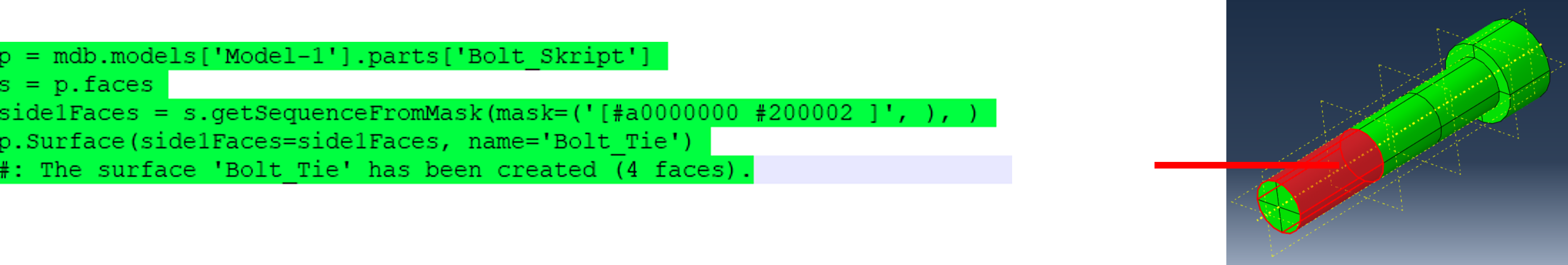
The same applies to the surfaces for the connection to the component via a TIE constraint. We want to replace the getSequenceFromMask created by the Macro Recorder, see image below, with a more general formulation.
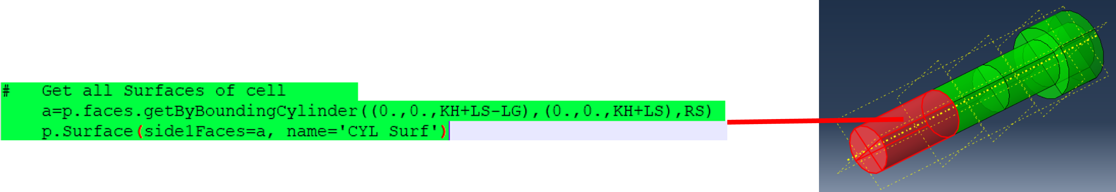
To define the areas independently of their numbering, a few more steps are required, which, as before, must be added to the script in the kernel and replace the code from the macro recorder shown above. First, the following command selects all faces of the front partition. ATTENTION: Due to a bug in V2024, the search range of the cylinder must be increased by a small amount (0.00001) Additional step #1
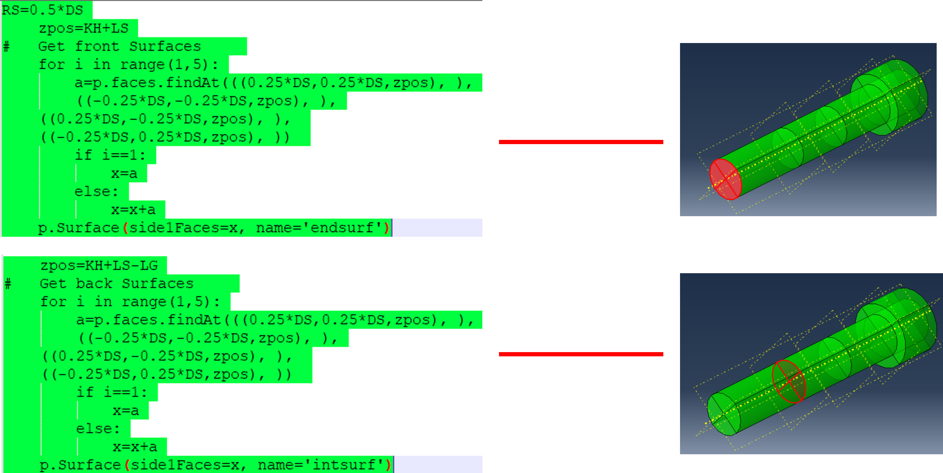
Selection of the surfaces on the two end faces, additional steps #2 and #3
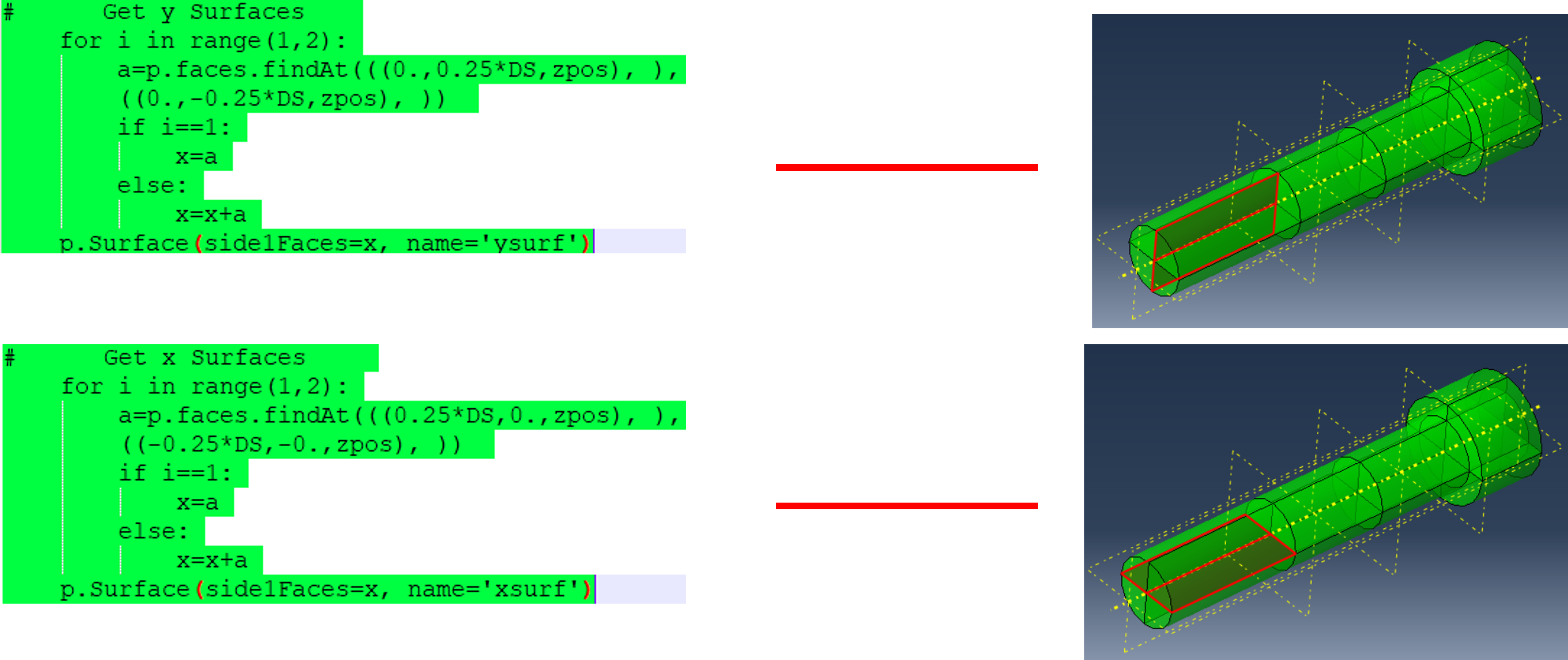
Selection of inner vertical and horizontal flats, additional steps #4 and #5
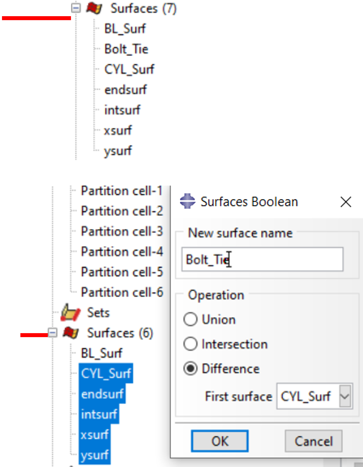
The areas created can now be found in the part tree.
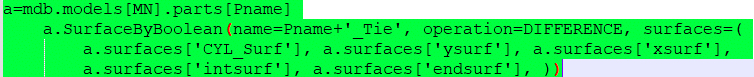
Additional step #6: Create the surface Bolt_Tie by Boolean operation: Subtract the surfaces endsurf, intsurf, xsurf and ysurf from the surface CYL_Surf (right mouse click on the selected surfaces). In the script, Bolt_Tie becomes “Pname+Tie”.
Additional and final step #7: The now redundant areas are deleted
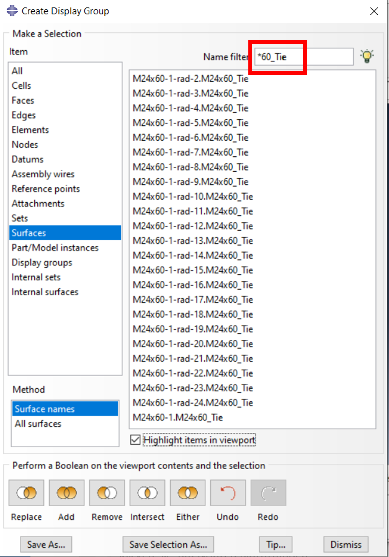
If many instances of one or more screws are required, the connection to the components can often be combined. In this example, the screw has the name “M24x60”. The surfaces for the connection from the threaded surface of the screw to the part, with standardized name “Pname+_Tie”, can now be easily combined into a single surface without the need to select the instances. Select these surfaces via the filter in “Create Display Group” (*-filter is helpful) and save individual surfaces, e.g. “M24x60_Tie_Secondary”.
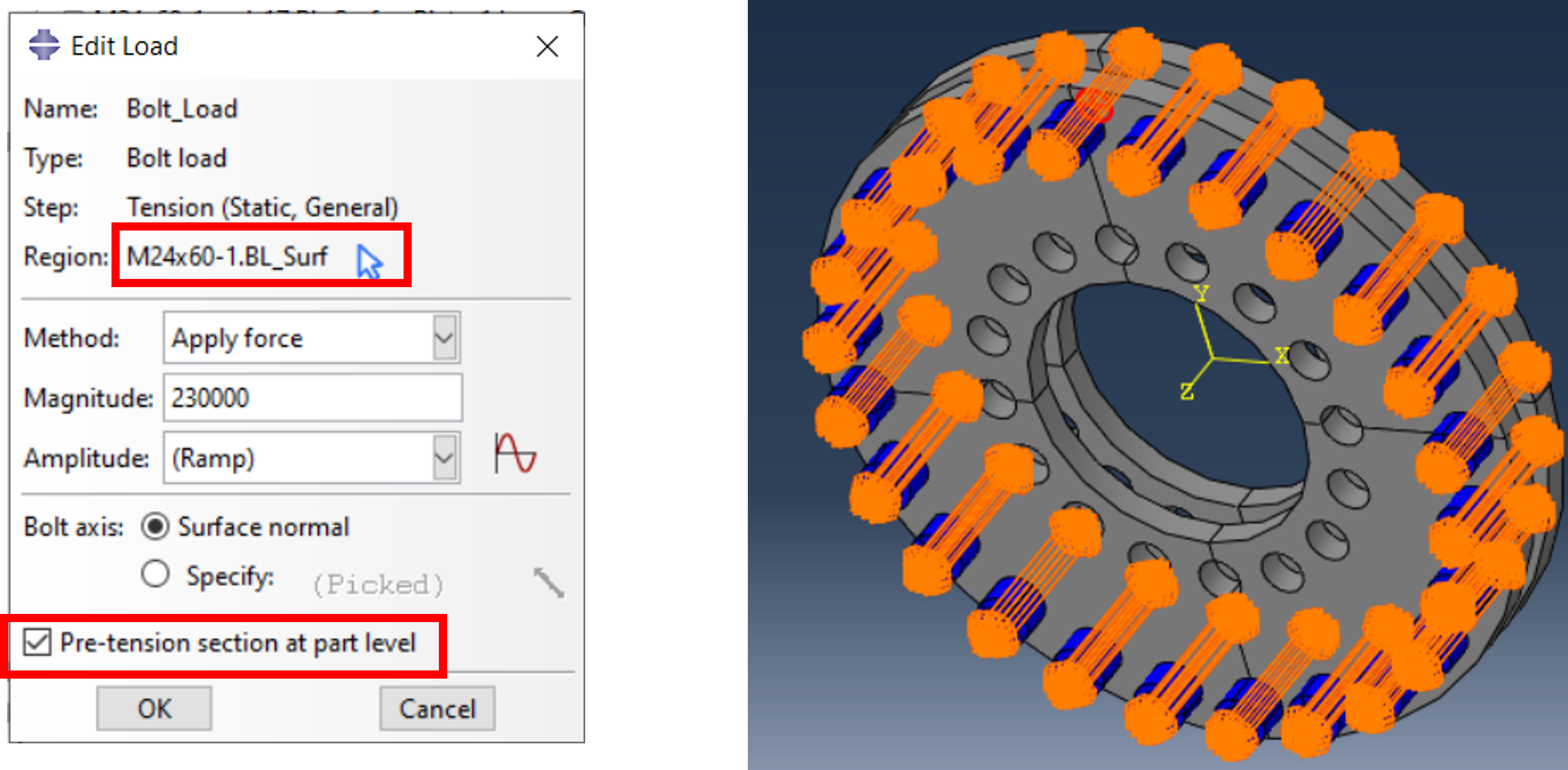
The screw load can now be applied just as easily without having to select the instance. To do this, just select the surface “‘Pname’+BL_Surf” and apply the force or displacement (depending on the method). By activating ” Pre-tension section at part level” the force is applied to ALL screws. .
We are happy to provide you with the plugin. We also have a variant with mother. Unfortunately, we cannot provide a download link yet. Please use the contact option below. A request does not commit you to anything, just as we cannot take responsibility for the use of the plugin. Bolt_without_Nut (bolt without nut, as described above) (download link/authorization required) Bolt_with_Nut Bolt with nut (download link/ /authorization required)