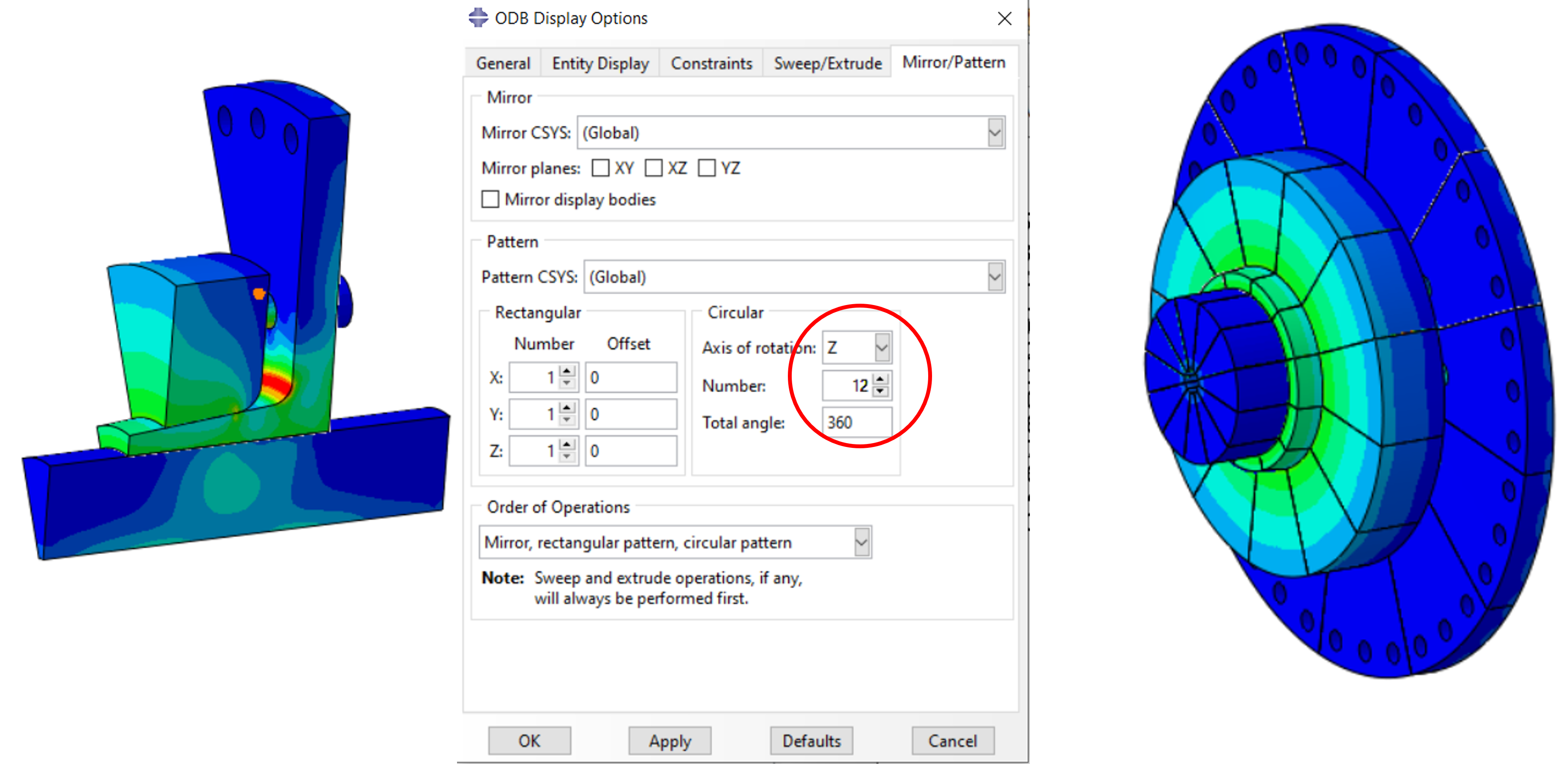
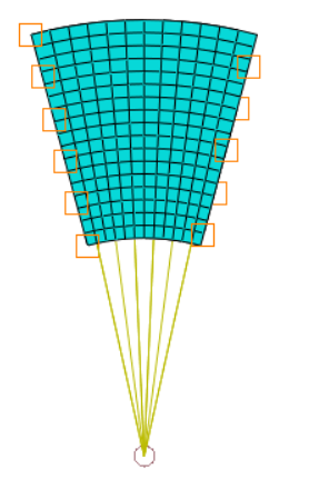
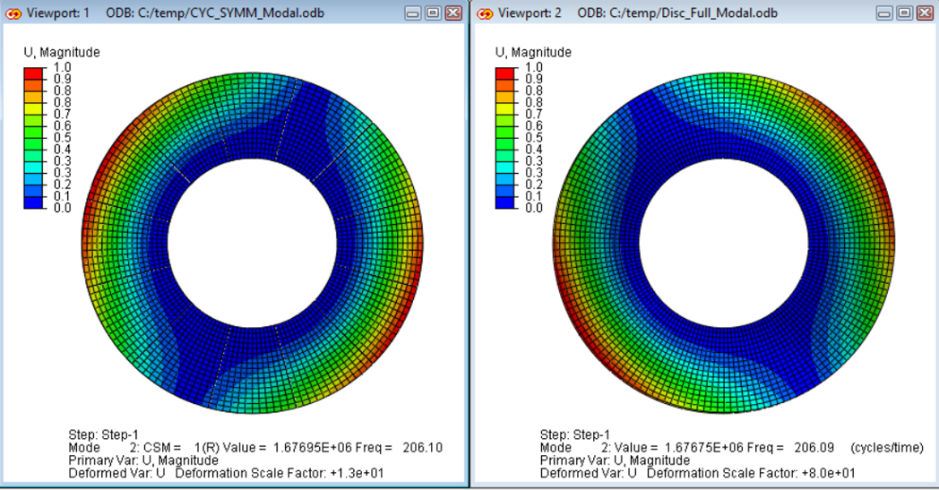
Cyclic symmetry finds application in the linear/nonlinear analysis of structures that can be divided into n equal substructures when orbiting about a given axis of rotation. For this purpose, it is sufficient to determine the solution for a substructure (so-called sector).
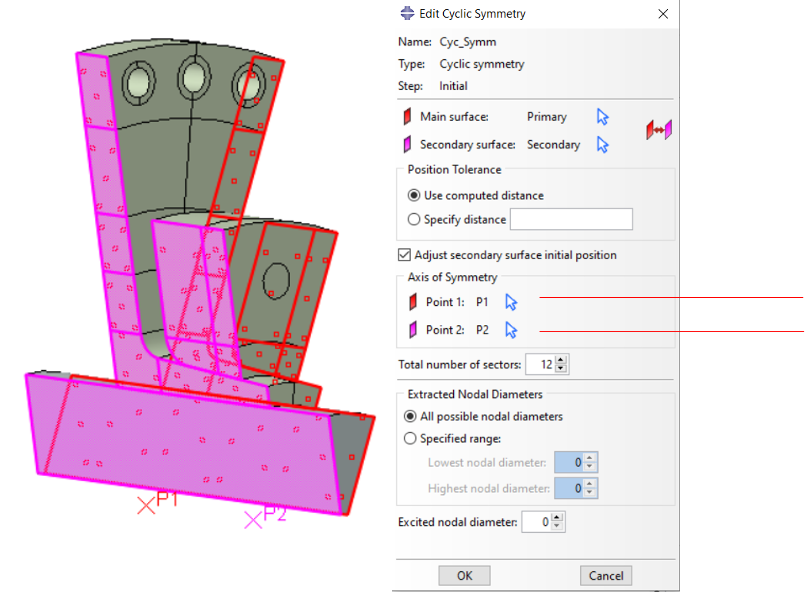
The procedure is simple: a cyclic sector is cut out of the overall structure. Cyclic symmetry is defined at the intersections at the Primary and Secondary surfaces via an interaction in the INITIAL STEP. Instead of a Surface, a Node Region/Geometry can also be used.
It is irrelevant whether the crosslinks at the Primary and Secondary Surface are identical, but care must be taken that the finer crosslink is always assigned to the Secondary Surface.
There are restrictions with regard to the loads, which are explained in more detail in the first example.
Furthermore, it is possible to transfer the obtained stress and deformation state to a 360° overall model in order to then apply non-cyclic symmetric external loads, such as bending (is content of a separate paper, see also *SYMMETRIC MODEL GENERATION, *SYMMETRIC RESULTS TRANSFER).
The following two examples show how cyclic symmetry is applied and what advantages it has. The examples were created with Abaqus/CAE. We will be happy to provide you with the CAE file.
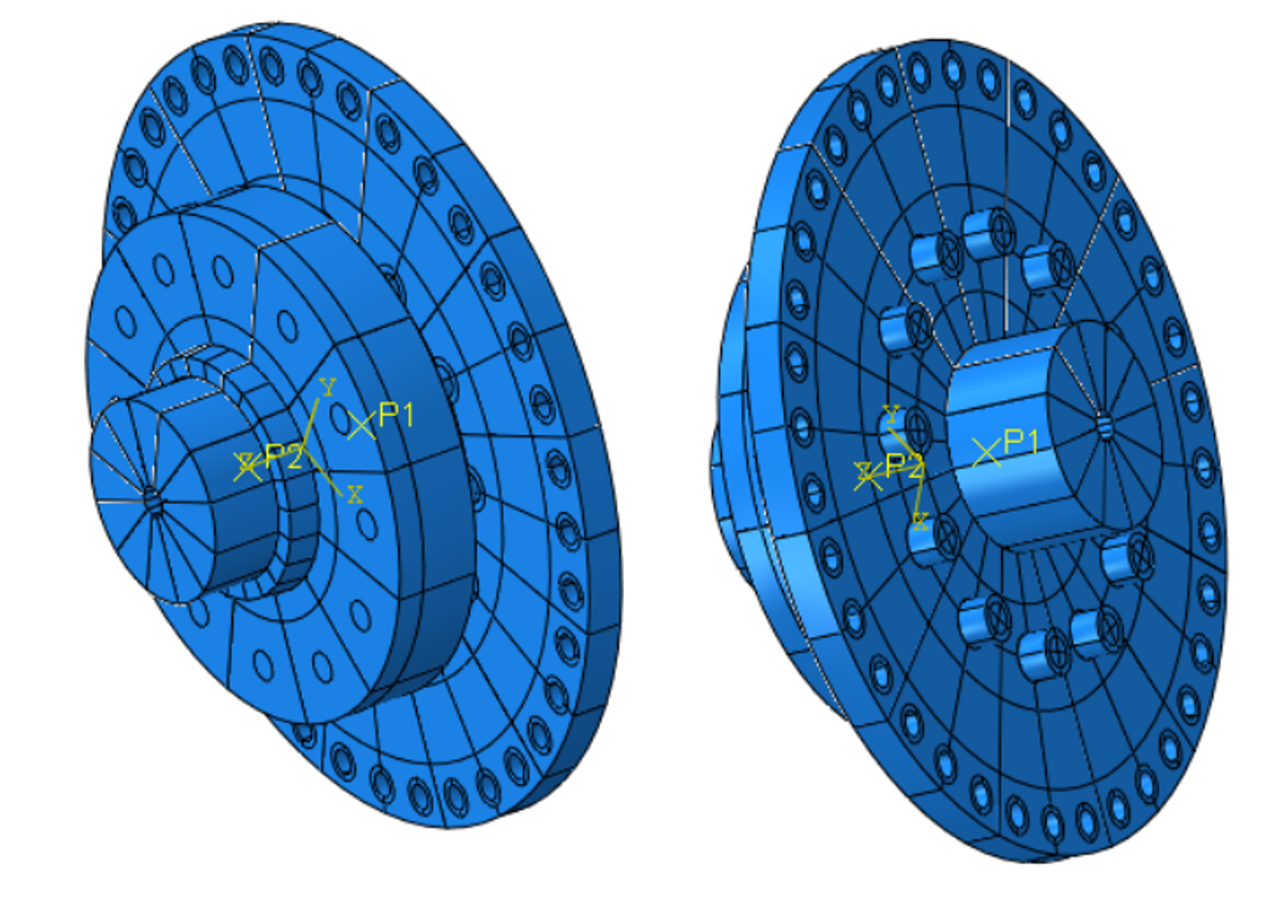
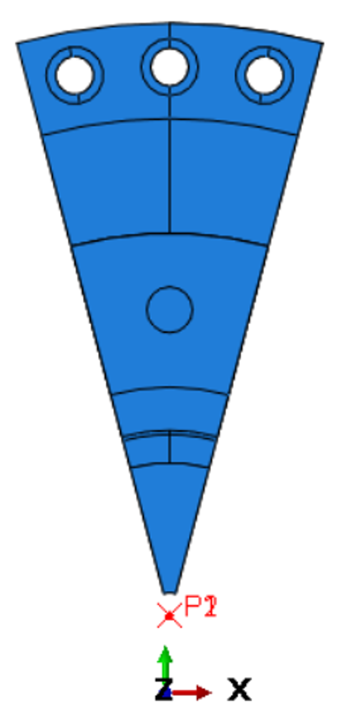
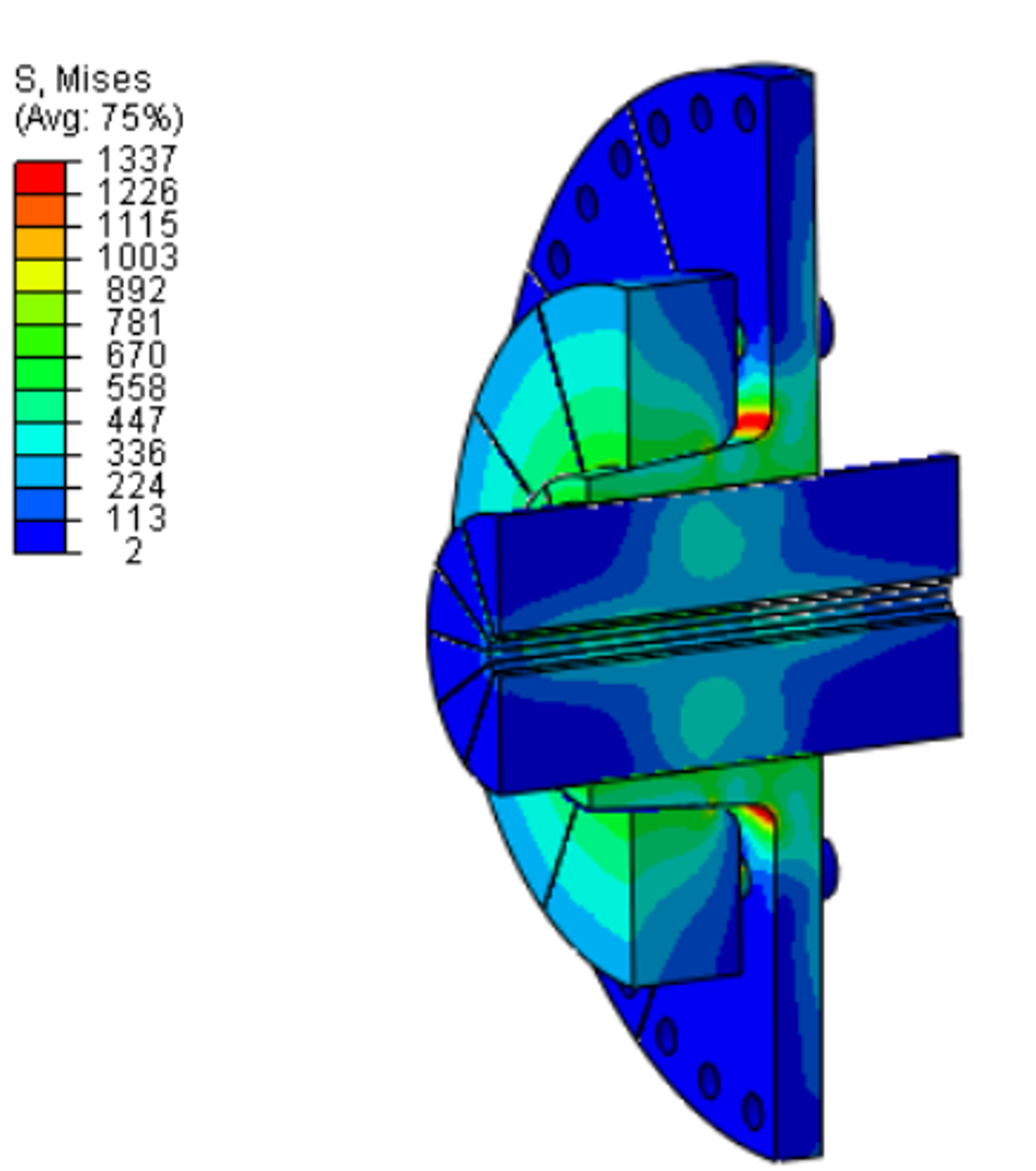
From a full model of a shaft to be clamped with an outer part, it follows that a 30° cutout is cyclically symmetrical. It results in 12 cyclic symmetrical parts. For one partial model and one full model the calculation is built.
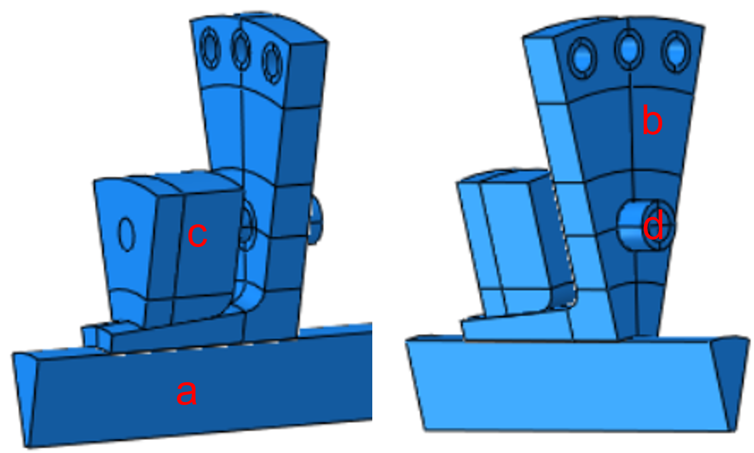
The inner surface of the shaft (a) is coupled to a reference point on the axis of rotation via node coupling of the Kinematic type. This reference point is fixed via a boundary condition.
By bracing the inner part (b) with the outer part (c) with a bolt force and the taper of the outer part in the area of the shaft, the inner part, outer part and shaft are pressed together. The step is defined as a Static, General with non-linear geometry.
While practically all loads (centrifugal force, temperature…) can be applied to the sector, this does NOT apply to non-symmetrical forces, moments and displacements.
It basically applies:
The deformation of the Secondary Surface follows the deformation of the Primary Surface with respect to the symmetry axis
Valid forces, moments, displacements, torsions:
CF1, CM1,U1,UR1 : No
CF2,CM2,U2,UR2 : No
CF3,CM3,U3,UR3 : Yes
The applied bolt force acts in the 3-direction.
Forces and/or torques must be divided in relation to the solid model
by the number of sectors !
To determine the stiffnesses, the reaction forces/moment of reaction must be
multiplied by the number of sectors !
The calculations of the model with cyclic symmetry and a full model are to be compared.
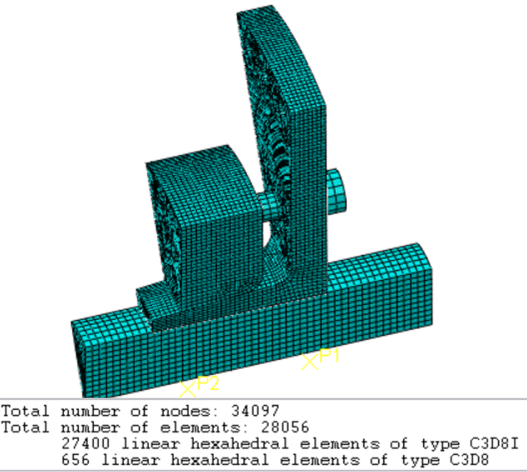
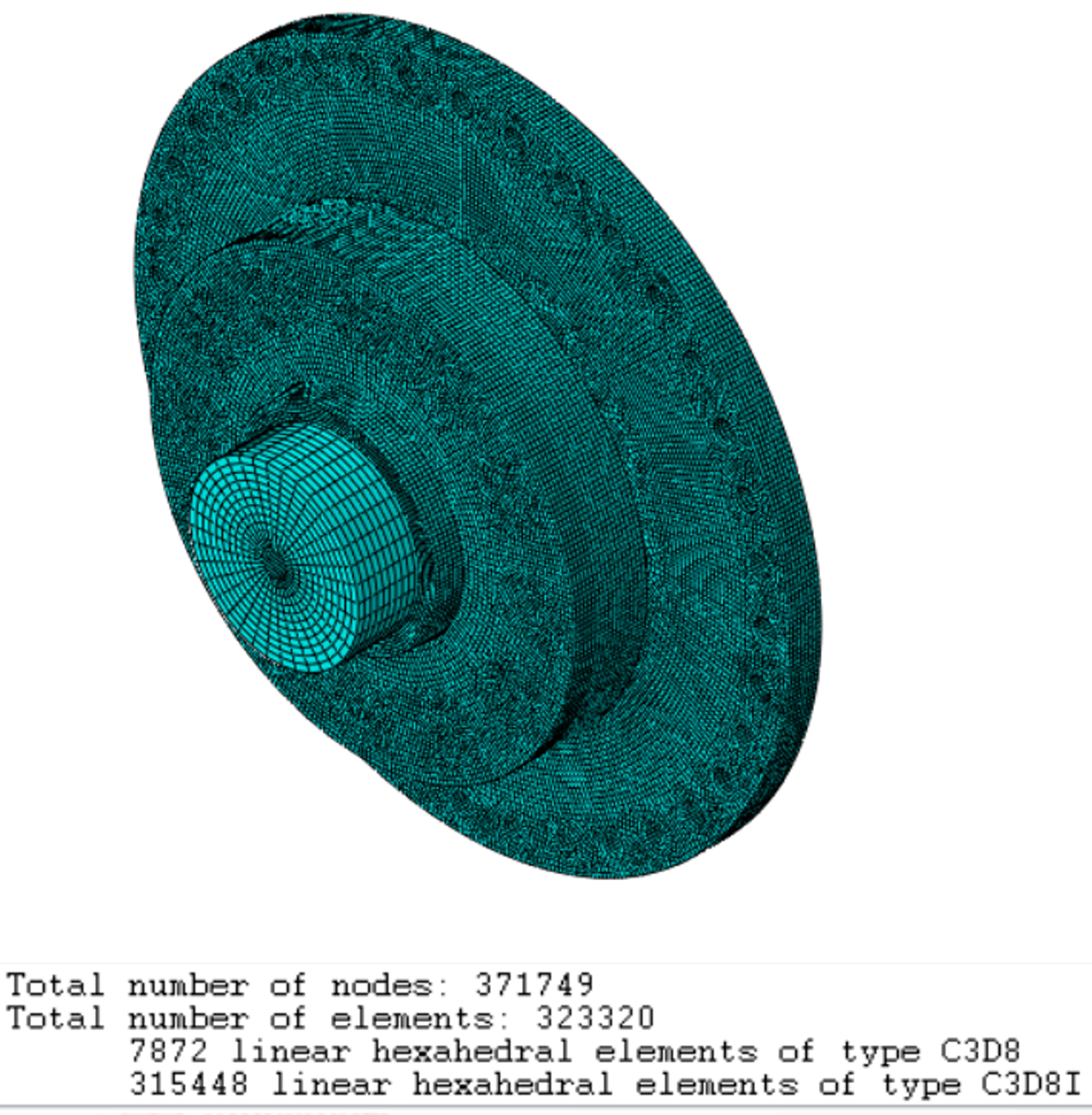
C3D8I elements were predominantly used for the meshing (except for the screw). There is not quite a factor of 12 in the number of elements due to slight differences in meshing
The calculations were performed on a laptop (HP Z- Book, 4 cores, 32 Gb RAM with GPU support). There are differences in computing time and memory (CPU RAM) requirements with a factor of > 12. However, both models scale similarly.
If boundary conditions are on the secondary surface of the cyclic symmetry, a warning message is displayed. The boundary conditions are automatically disabled by Abaqus/CAE, but they can also be deselected by the user.
However, in the Example 1, Secondary Surface nodes are used in a node coupling, see figure below.
If nodes of a node coupling are located on the secondary surface of the cyclic symmetry, a warning message is issued. These nodes are automatically removed from the coupling by Abaqus/CAE, but they can also be deselected by the user.
Here: Boundary conditions on inner surface of shaft overlap with Secondary surface.
