Abaqus offers a wide range of elements for the different analyses. Assistance for the correct selection of elements is provided by the manual, (Dassault Systèmes, 2023) and (Reichert, 2018).
A small example shows that it always depends on the use case and the goals of a calculation which element type and which discretization should be used. The small example of a bending beam with point bending force shown here is a linear (geometry and material) case of structural mechanics. The example is intended to illustrate how the results change depending on the selected element and discretization. So far, only hexahedral elements have been considered.
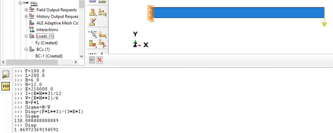
The bending beam, 200 mm long, 6 mm wide and 12 mm high (see picture below), is held at one end in the x- and y-directions and in the center plane in the z-direction. The shape of the restraint is intended to reduce the occurrence of stress peaks at the restraint. The material used is steel. The load is applied at the top two corners of the other end in point form (F = 2 x 50 N). Analytically, the displacement in y-direction (u2) and the bending stress (corresponding to S11) at the clamping point are determined. The console (Kernel Command Line Interface) of Abaqus/CAE can also be used for the calculation of the analytical solution.
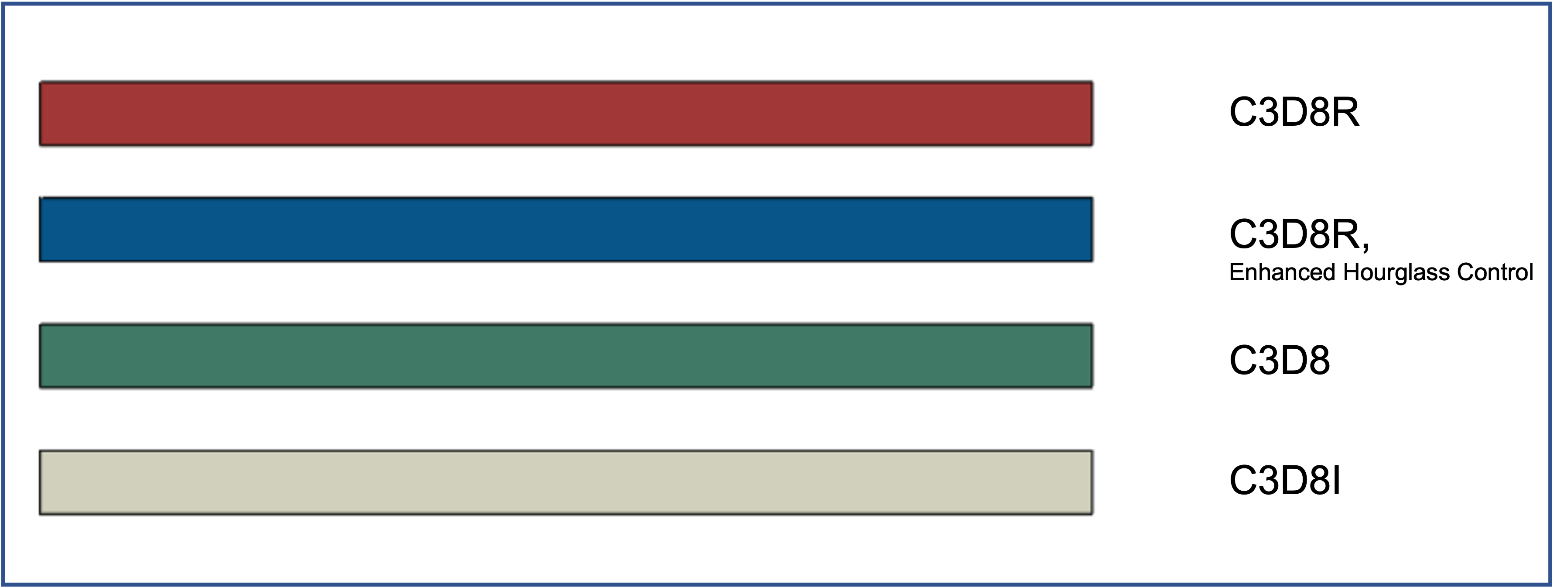
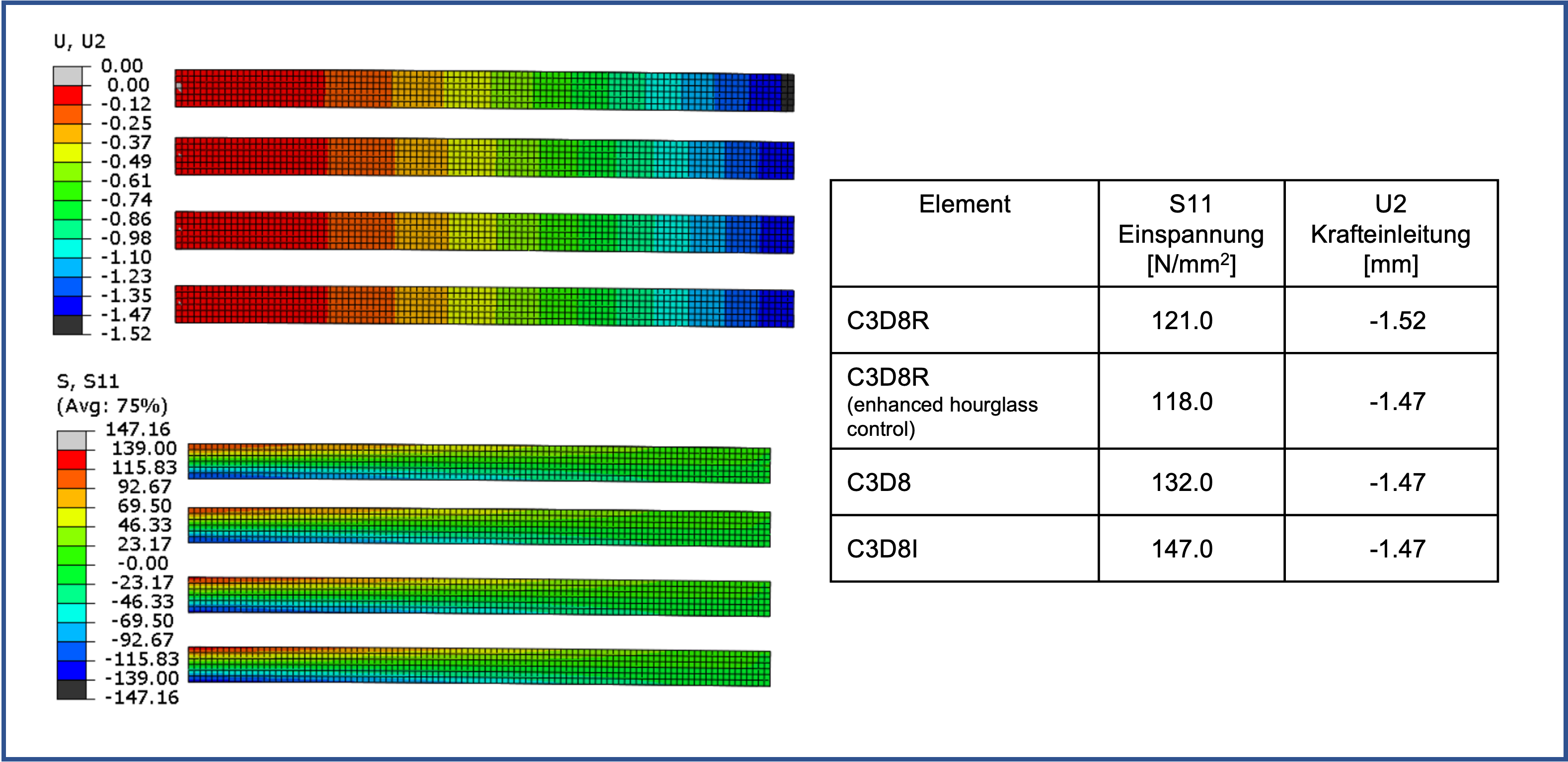
4 parts of the same bending beam are used to view the results of different element types at the same time,
The element types used were (from top to bottom) C3D8R, C3D8R with Enhanced Hourglass Control, C3D8 and C3D8I.
- C3D8R: 8 nodes linear hexahedral element with reduced integration (1 integration point / element )
- C3D8R: as above, with Enhanded Hourglass Control
- C3D8 : 8 nodes fully integrated hexahedral element (8 integration points / element )
- C3D8I : 8 nodes modified fully integrated hexahedral element ( 8 integration points / element )
(see also [3])
All calculations were performed using Abaqus/Standard v2022 HF6. A Static General Step was used, leaving NLGEOM = OFF.
If one compares displacements and/or stresses between analytical and numerical solution, the problem always arises at which points to compare. Displacements are calculated at the nodes and can be read directly there. However, stresses (and strains) are calculated at the integration points. However, these are not located on the surfaces of the elements and so a direct comparison is not possible here. Here we use the values extrapolated to the nodes on the surface, which always results in some error.
For the different element types, the element size of the model was varied in each case (via the specification in Mesh/Seed/Part).
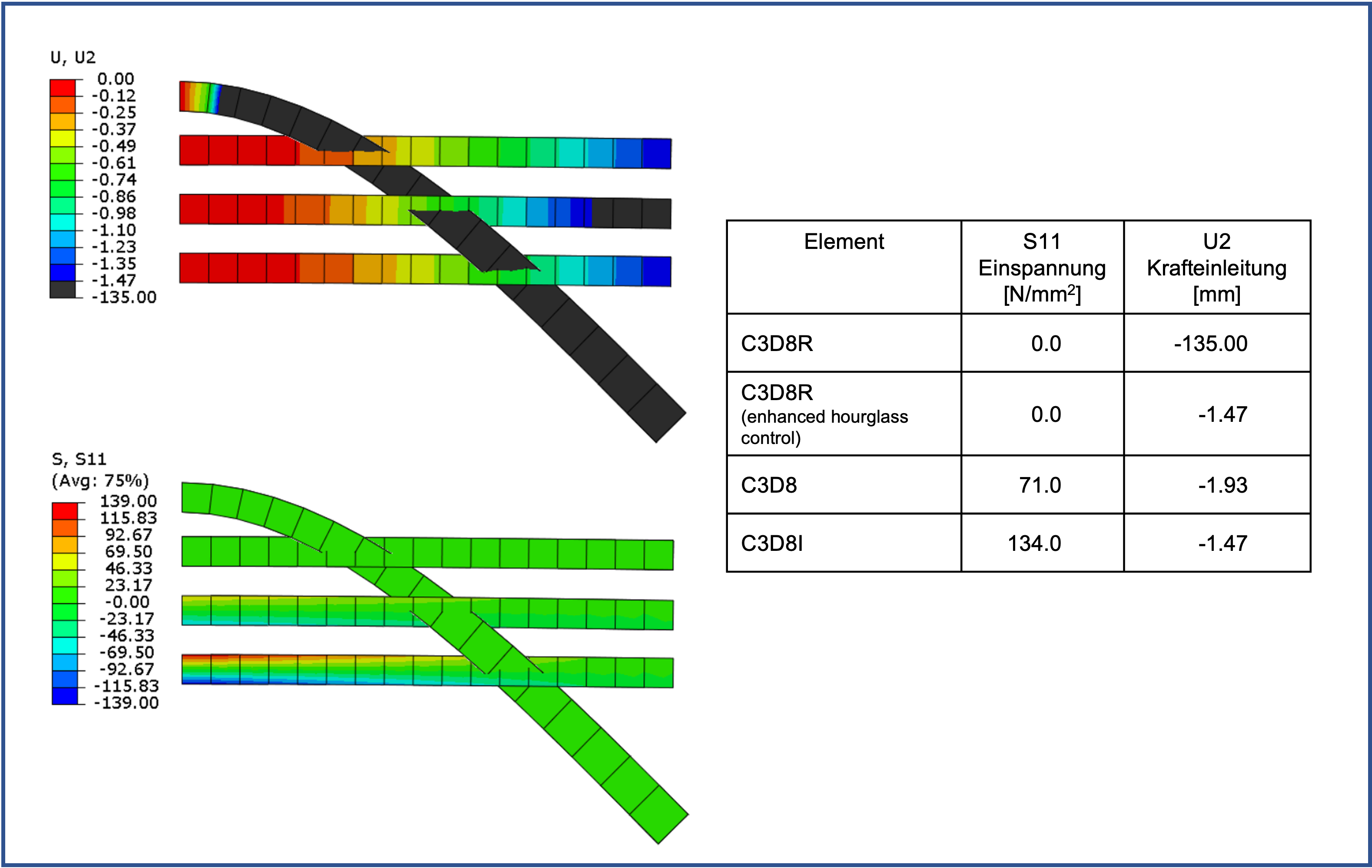
With quite sparse discretization with an edge length of 12 mm, an element over the height of the beam cannot represent the stress profile due to the bending.
In addition, the reduced integrated element with Default Hourglass Control behaves very softly. Only the C3D8I element provides a usable result here.
With an edge length of 8 mm and thus 2 elements over the height, the result is similar:
Only the C3D8I element shows a useful result.
With an edge length of 4 mm and thus 3 elements above the height, the results with regard to displacements become significantly better.
However, the suspense picture continues to be poorly presented.
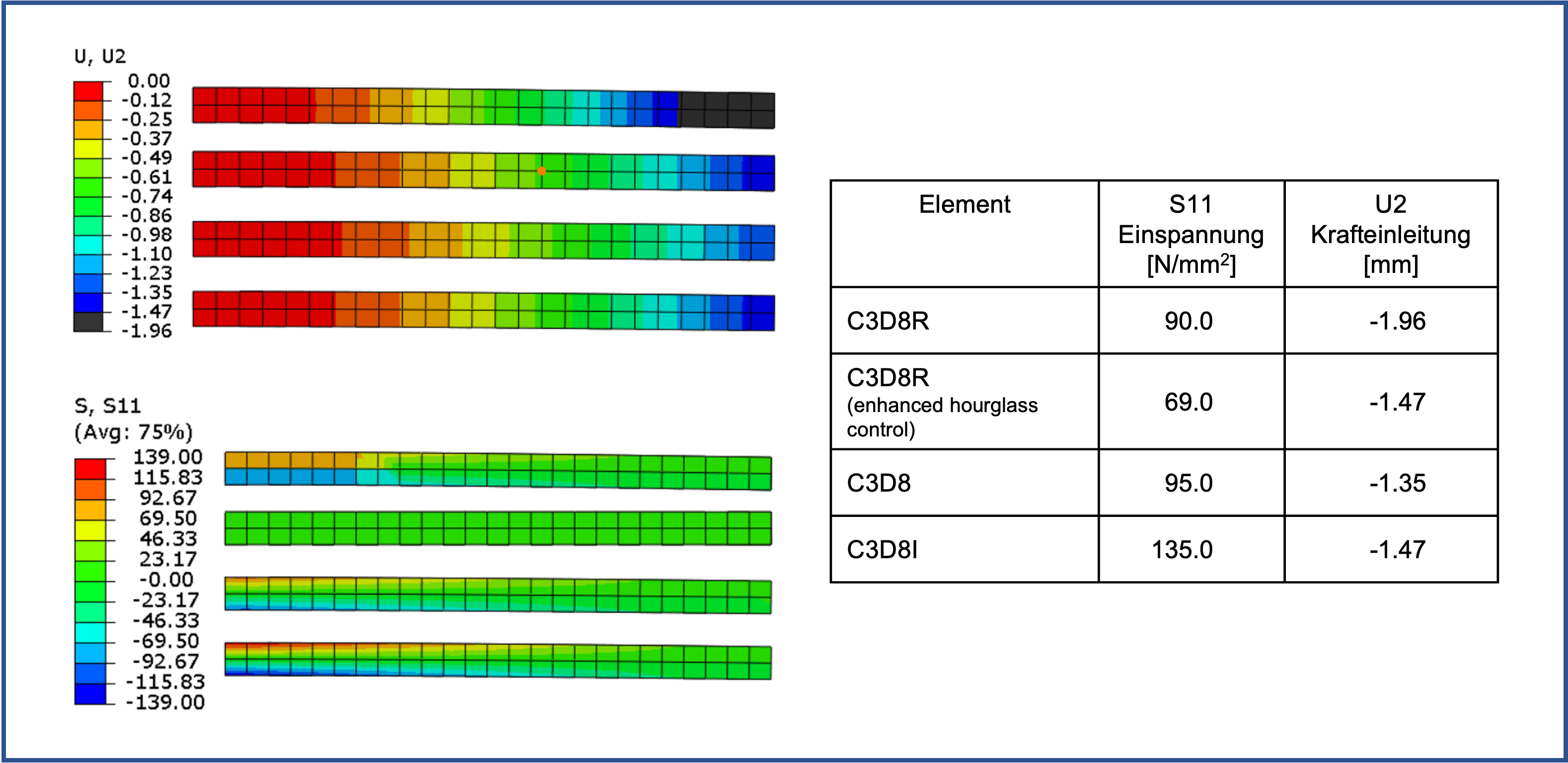
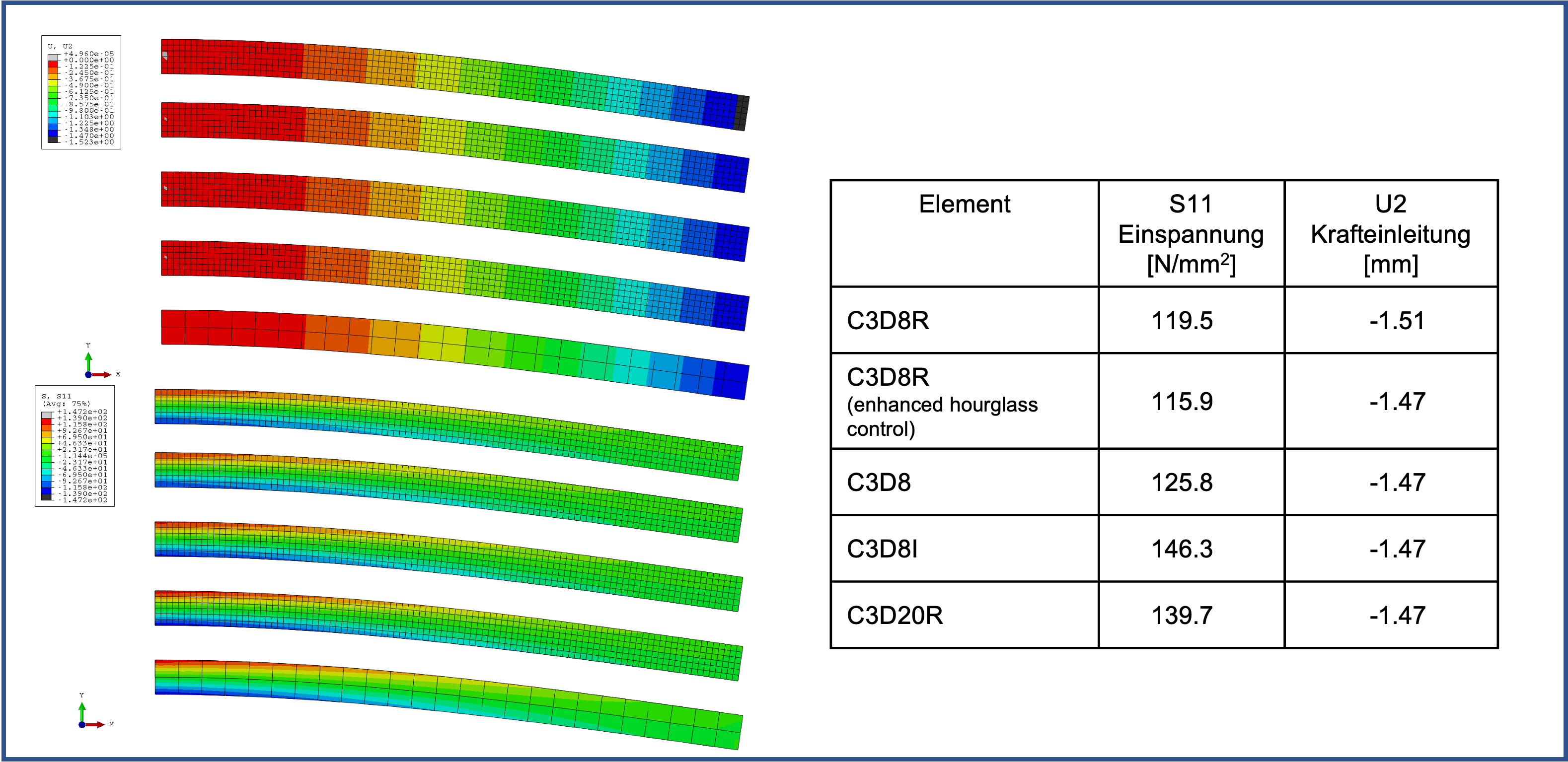
Only with an edge length of 2 mm and thus 6 elements is there a further improvement.
However, the reduced integrated elements still do not represent the stress pattern correctly.
This small example illustrates that in case of “wrong” element selection even a supposedly simple problem concerning stress evaluation is not correctly reproduced. Here, the C3D8I element represents the means of choice if one does not want to switch to square element approaches.
It should not go unmentioned that in Abaqus/CAE the C3D8R element is used as default. Certainly this element has its advantages for non-linear calculations and large deformations, but not for the linear application and small deformations shown here.
Basically, we want to continue to address this issue.
A short test with C3D20R shows that good quality results can be achieved even with much coarser discretization.
Unfortunately, the element for all finite element calculations does not exist. Thus, depending on the problem to be calculated and the goals of a calculation, the user should determine the “right” element and the correct discretization himself. The user is supported by the manual of the software and by individual contributions of different authors. With this paper we want to show how strongly the results of a simple linear calculation of a bending beam can depend on the choice of the element type and the discretization. In this simple case, C3D8I or C3D20R are the means of choice. More articles on this topic are to follow.
In part, this text and illustrations shown are based on research of evaluated literature. If this is the case, the sources are marked in the text by a number, e.g. [2], and the source is listed here.
In part, however, the sources listed here should simply be understood as recommendations for further reading.
