Press-fit connections are standards for joining multiple components. They are used in almost all areas of mechanical engineering. A shaft-hub connection serves as an example here.
This post describes different possibilities for the simulation of press fits. First, 2 methods are presented: a geometric overlap of the CAD data and the calculation of an interference fit with non-overlapping geometry at the beginning. In addition, in both cases the contact model used is varied – a Surface/Surface contact and the use of General Contact. In this case, this results in 4 possible approaches to simulating such an interference fit.
The Abaqus version v2022 HF6 is used.
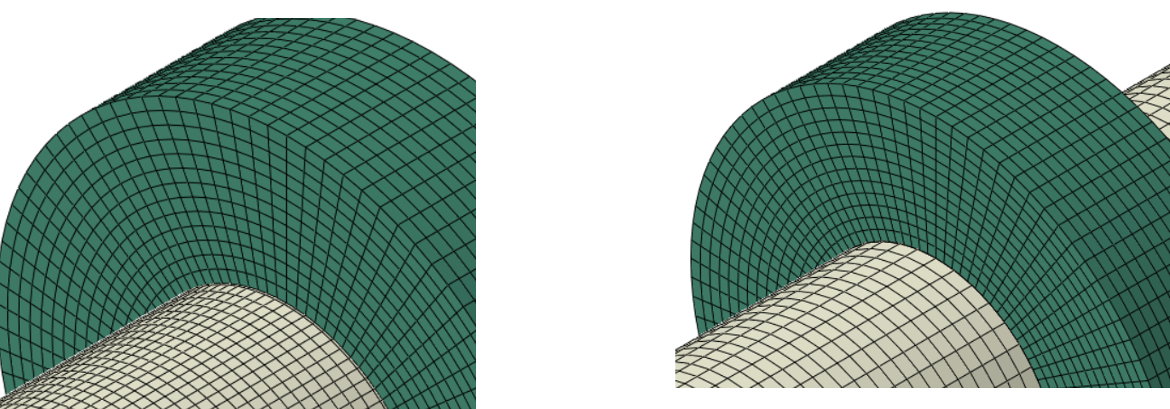
A shaft is fixed at both ends via coupling to a reference point, see picture on the right. A hub sits on this shaft. The outer diameter of the shaft is 200 mm.
At
Case A: the outer diameter of the shaft and the inner diameter of the hub are identical.
At
Case B: the hub has a smaller inner diameter (199.9 mm) than the shaft.
The contact surfaces are shown in the picture on the right. For the shaft the surface Shaft_Outer (left in the picture) and for the hub the surface Hub_Inner (right in the picture).
2 different methods are used:
– Surface/Surface Contact (Method A)
– General Contact (Method B).
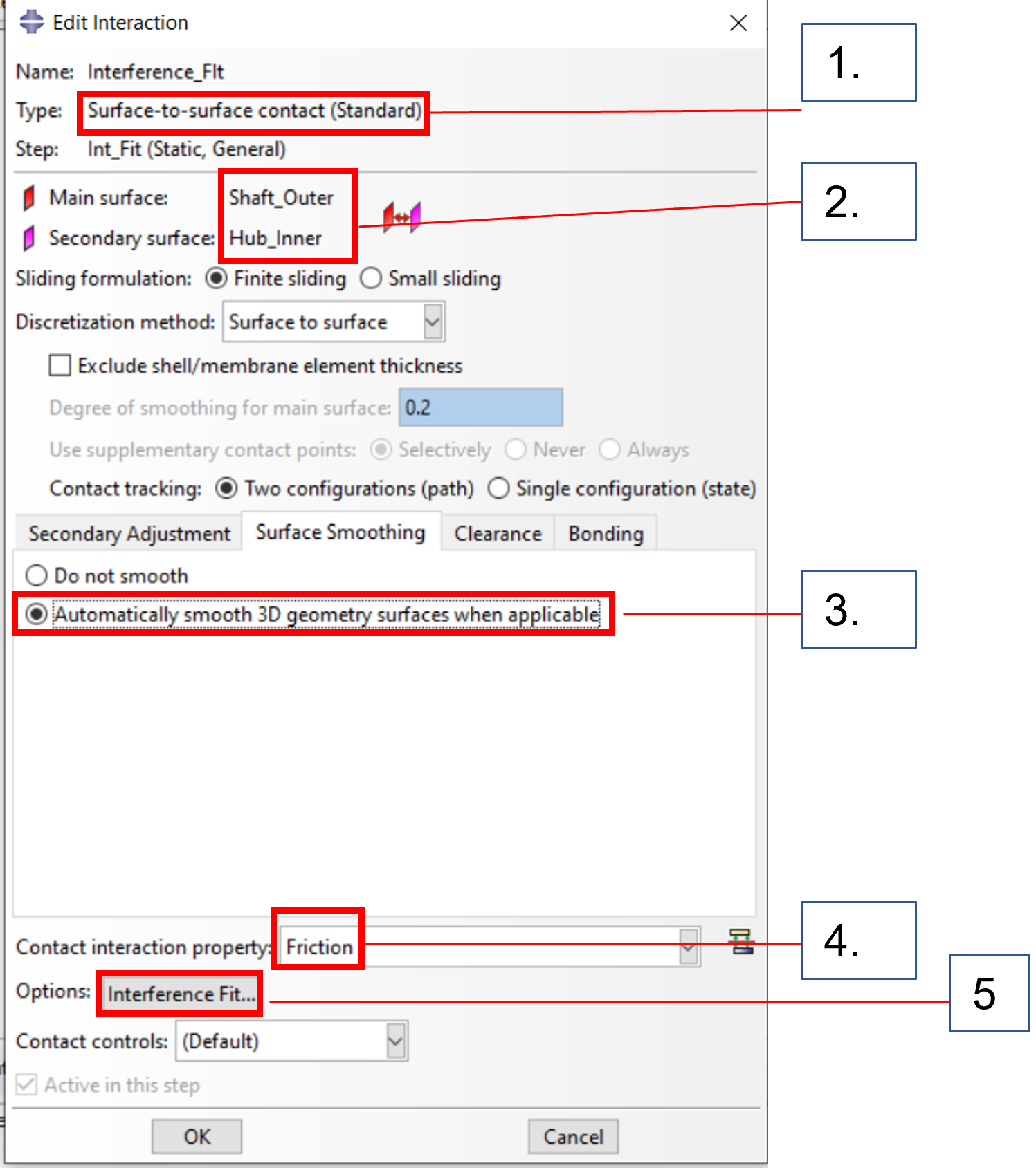
Step 1: Definition of the contact pair
1. selection of the method
2. surfaces of the contact pairing
3. activate smoothing , absolutely necessary in case of unequal element sizes
4. activate friction
5. continue to step 2
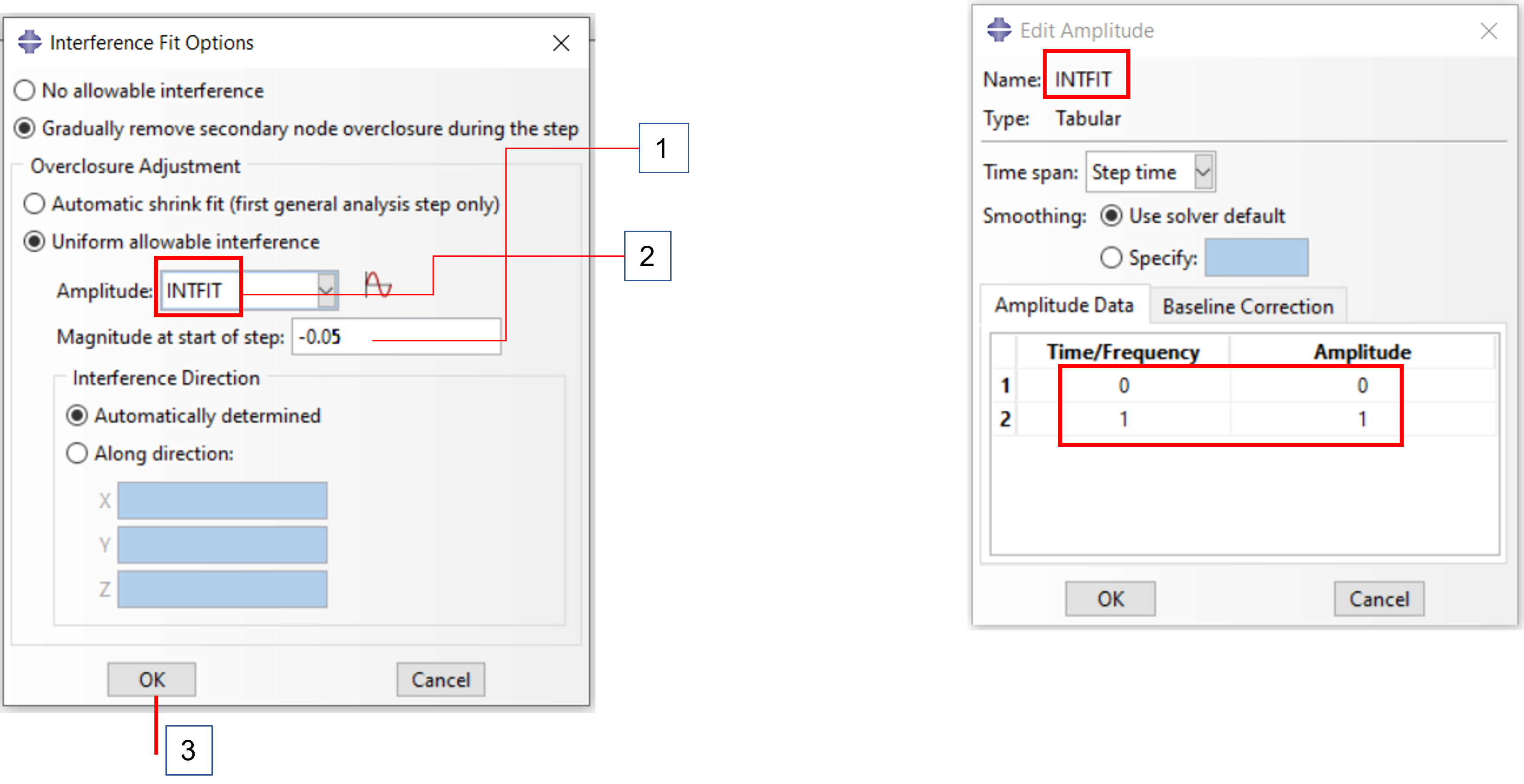
Step 2:
1. overlap : -5/100 mm
2. requires an amplitude
It can be created in this dialog.
Caution: It is then NOT automatically taken over, only by subsequent selection
3. then confirm and the interference fit is defined
Step 1: Definition of the contact pair (Identical to case A)
1. selection of the method
2. surfaces of the contact pairing
3. activate smoothing , absolutely necessary in case of unequal element sizes
4. activate friction
5. continue to step 2
Step 2: Define overlap
Geometric overlap, only valid in the first step !
Then confirm and the press fit is defined
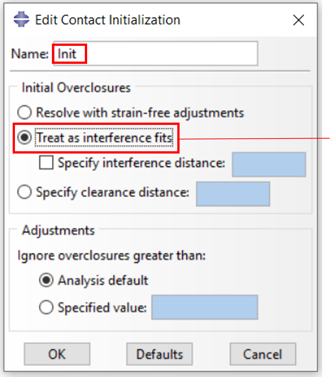
1.selection of the method
2. switch on friction and open dialog for initialization
Definition of the overlap
Enter overlap dimension, this MUST be > 0
Definition of the contact pair
Select contact pair for initialization here
Confirm and exit dialog
The press fit is now defined
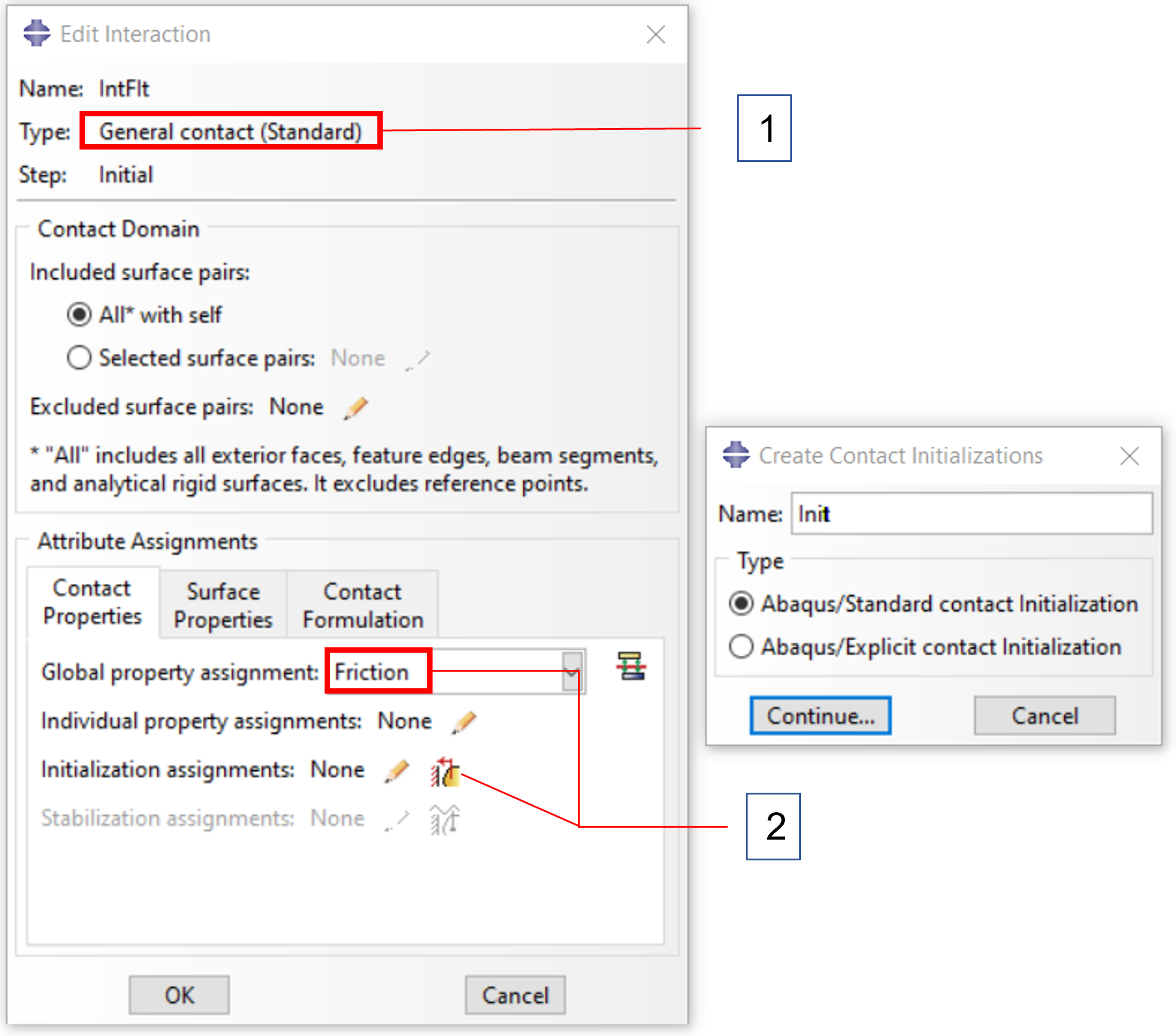
Step 1: Definition of the contact pair, Like Method B – Case A
1.selection of the method
2. switch on friction and open dialog for initialization
Step 2: Definition of the overlap
Geometric overlap is detected as pressing
Step 3: Definition of the contact pair, Like Method B – Case A
Here select contact pair for initialization and confirm with
OK to exit the dialog. The press fit is now defined
Method A – Surface/Surface Contact:
Case A: Coincident surfaces (left), Case B: Geometric overlap (right)
Method B – General Contact
Case A (left), Case B (right)
Method A – Surface/Surface Contact
Case A: Coincident surfaces (left), Case B: Geometric overlap (right)
Method B – General Contact
Case A (left), Case B (right)
An almost identical result is shown regardless of the contact algorithm used and the method to describe the overlap. In the event that the press-fit investigation is part of a Design Of Experiment (DOE), Case B is preferable, regardless of the method.
In real terms, press fits are often produced by enlarging a component by means of heating and then shrinking it on. This can be simulated just as easily. However, the heat transport itself is not simulated here.
In the present example, the shaft has an outer diameter of 200mm, the hub an inner diameter of 199.9 mm. To eliminate the overlap, the inner diameter of the hub must therefore be increased by at least 0.1 mm by heating.
In general :
D1=D0 (1+a*Dϑ)
Whereby :
D1= diameter after heating (200mm)
D0 = Diameter before warm-up (199.9mm)
a= coefficient of thermal expansion (here 12*10^-6/K)
Dϑ= Temperature difference in °K
Since in the present case no heat transport (radiation , heat conduction, etc.) is involved, the temperature can be selected without taking absolute zero into account. The minimum temperature required to heat the hub and the associated increase in internal diameter is therefore as follows:
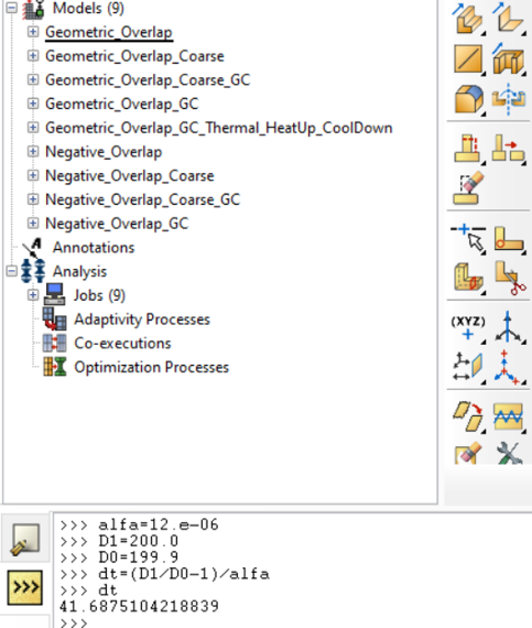
(D1/D0-1)/ a = Dϑ
The Command Line Interface is used to calculate Dϑ.
The hub must therefore be heated by at least the value of dt , so that its inner diameter at least takes on the outer diameter of the shaft.
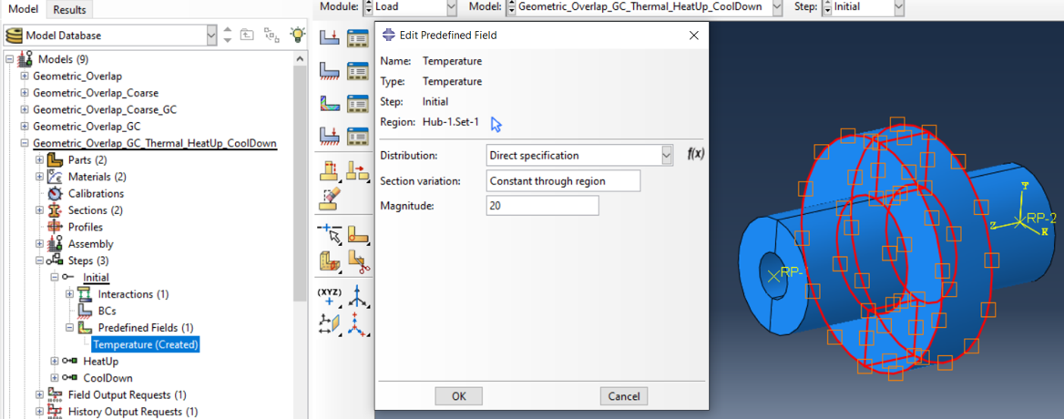
To perform the simulation, 2 load steps are used. Step 1 – HeatUp and Step 2 – CoolDown. The hub is heated via the temperature control of the nodes. Since this is a static procedure, there are no temperature degrees of freedom at the nodes. The control is done by the temperature in the predefined fields (*TEMPERATURE in the input deck).
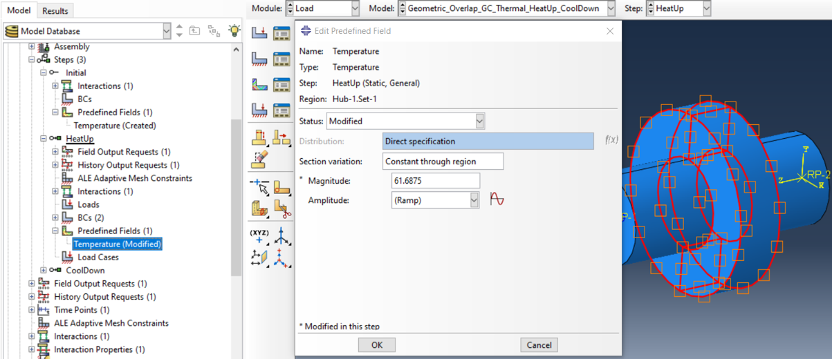
First, a predefined field of type Temperature is created for the hub in the Initial Step with RT=20°C
Then, in the first step, the temperature RT is increased by at least dt. Here it is useful to request a Field Output NT for the temperature at the nodes.
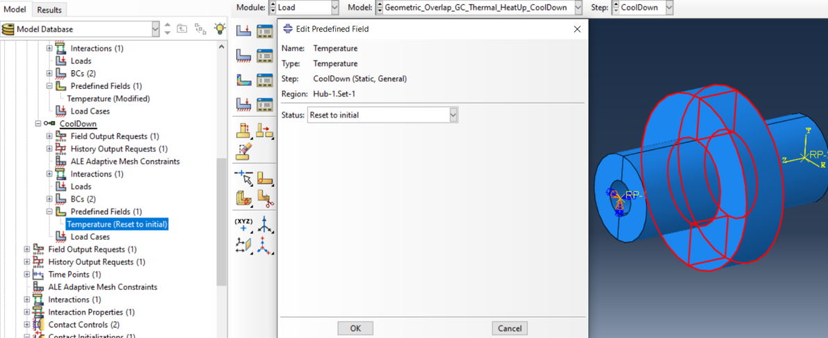
To be cooled down again to RT in the second step…
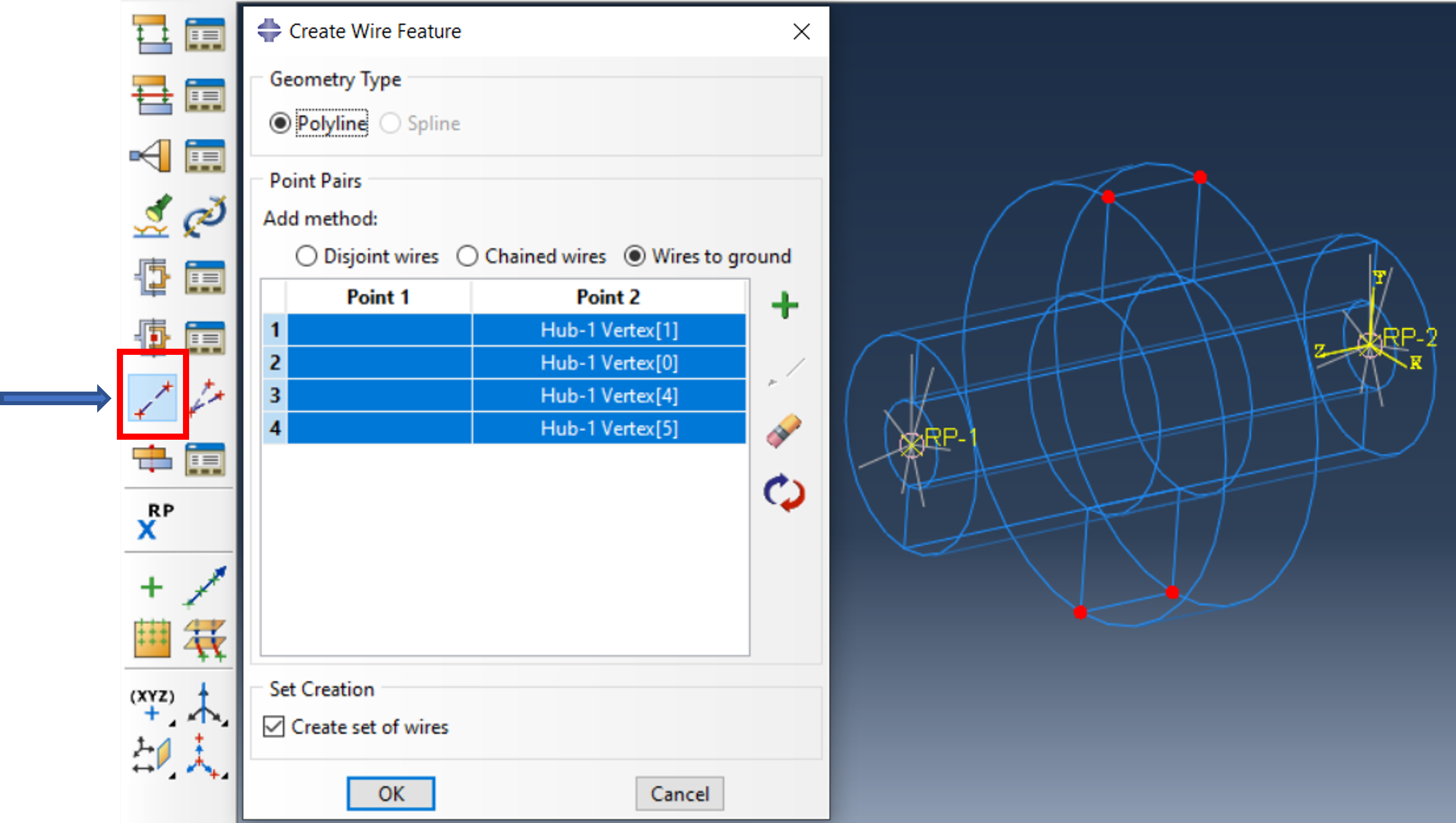
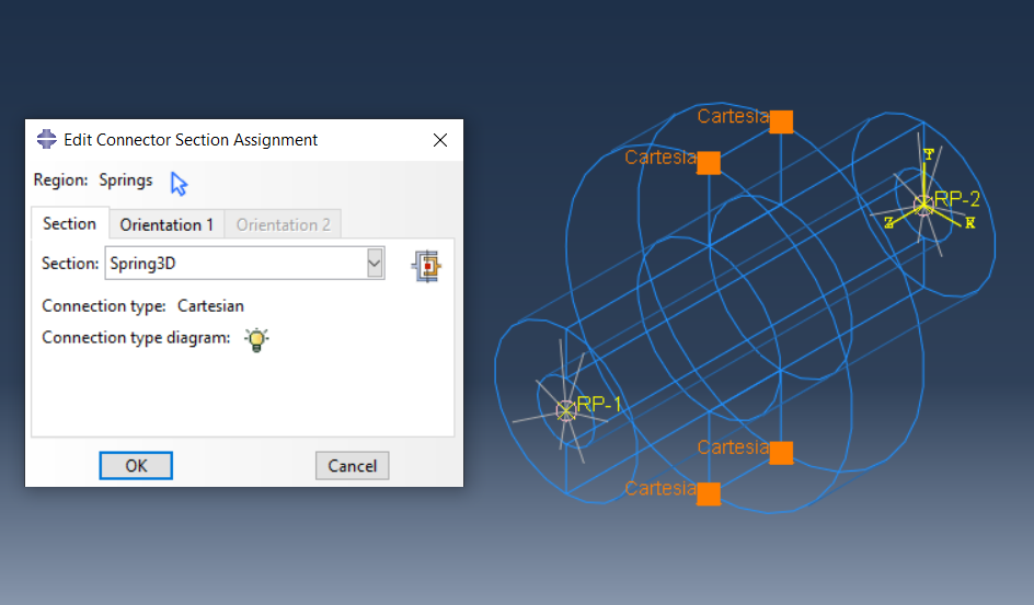
To avoid rigid body movement, the hub must be supported in some way, here with springs (Wires to Ground).
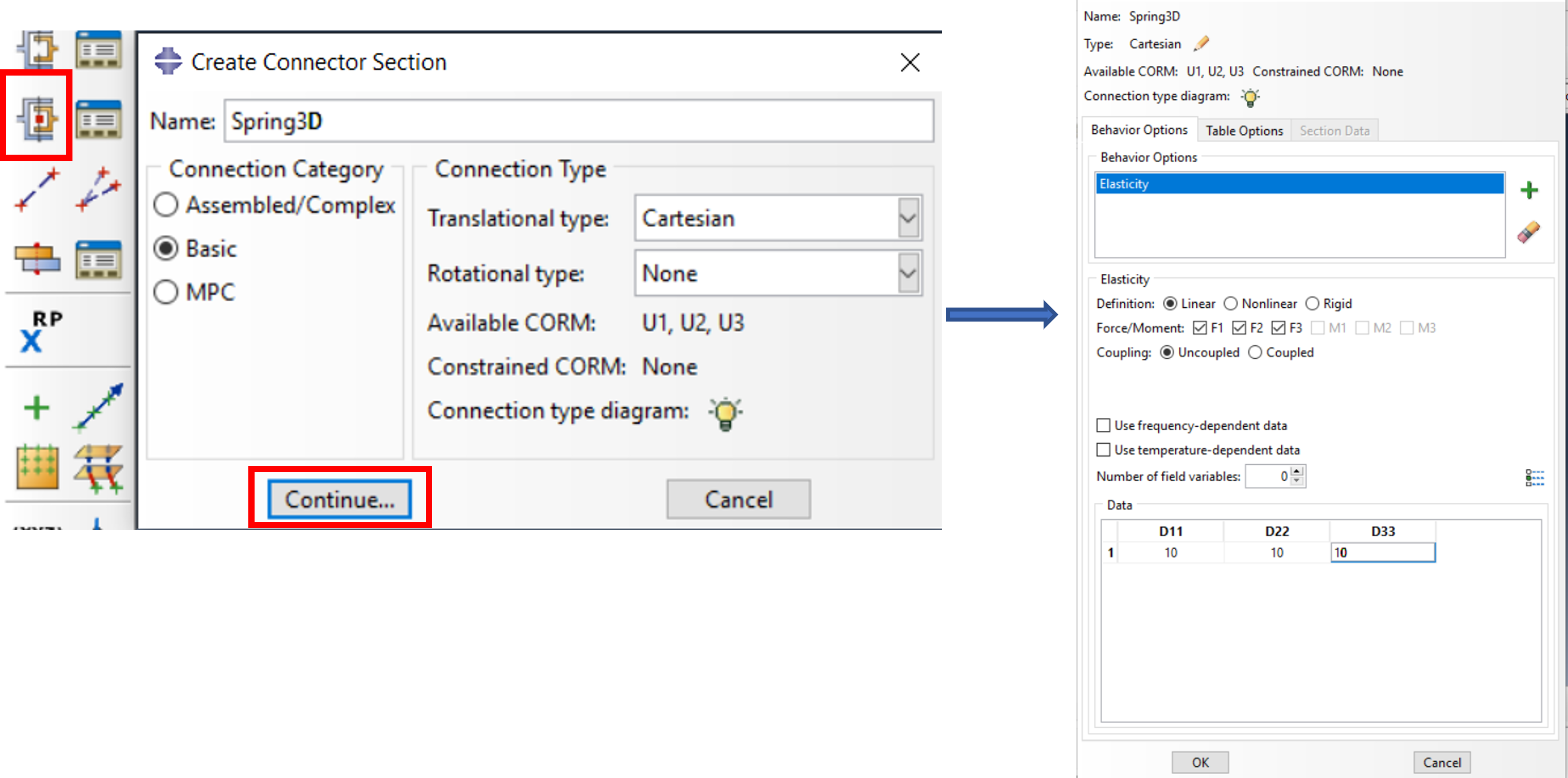
Now a Connector Section is created, here of type Basic > Cartesian with 3 translational stiffnesses
The Connector Section is now assigned to the previously created springs (Wires)
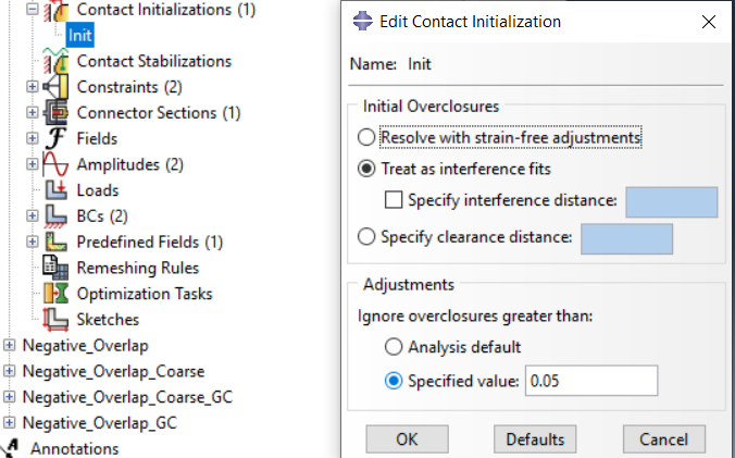
Here, too, the geometric overlap must be defined in the first step by means of a contact initialization, but it is resolved by the temperature expansion in the first step.
(Tip: Alternatively, you can also work with CONTACT EXCLUSION in the first step and activate the contact between shaft and hub via CONTACT INCLUSION in the second step. Maybe this is even more elegant …)
This Contact Initialization is now applied to the contact pair from hub to shaft.
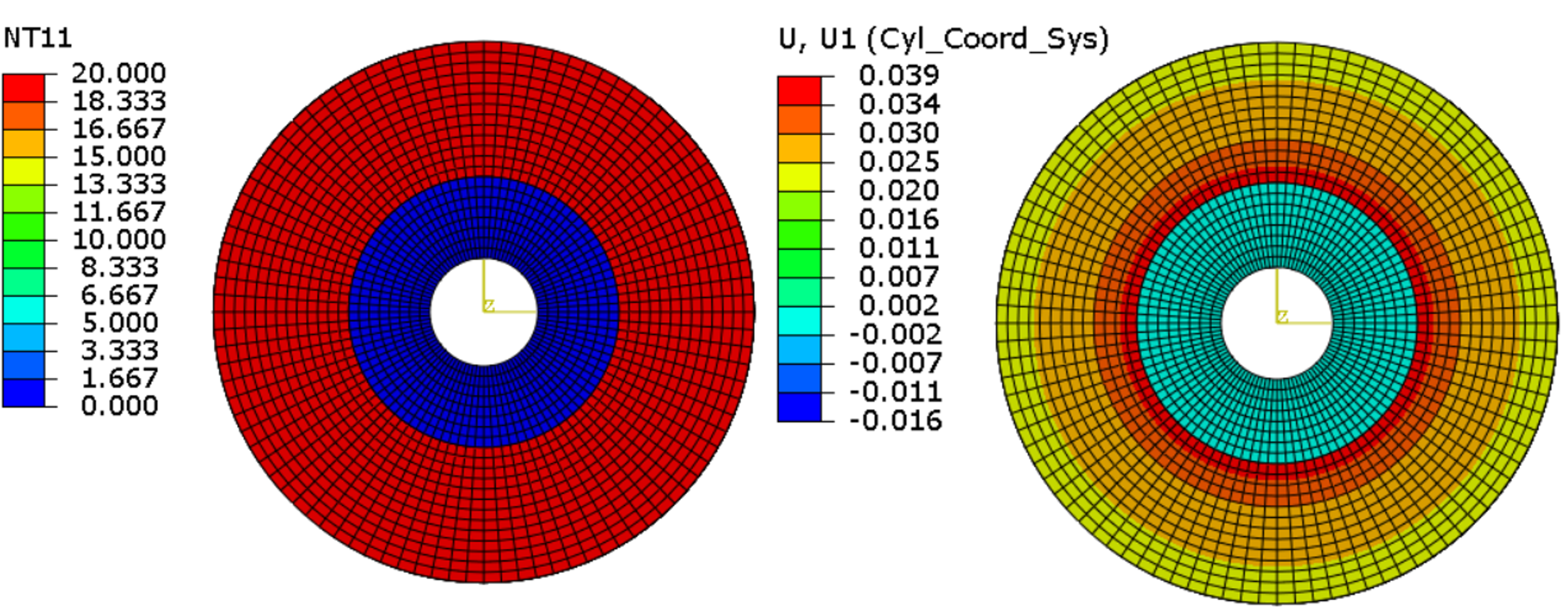
Temperature (left) and radial expansion (right) in step 1 ( heating), Radial expansion at the inner diameter of the hub: 0.05mm
Temperature (left) and radial expansion (right) in step 2 ( cooling), Radial expansion at the inner diameter of the hub: 0.039mm
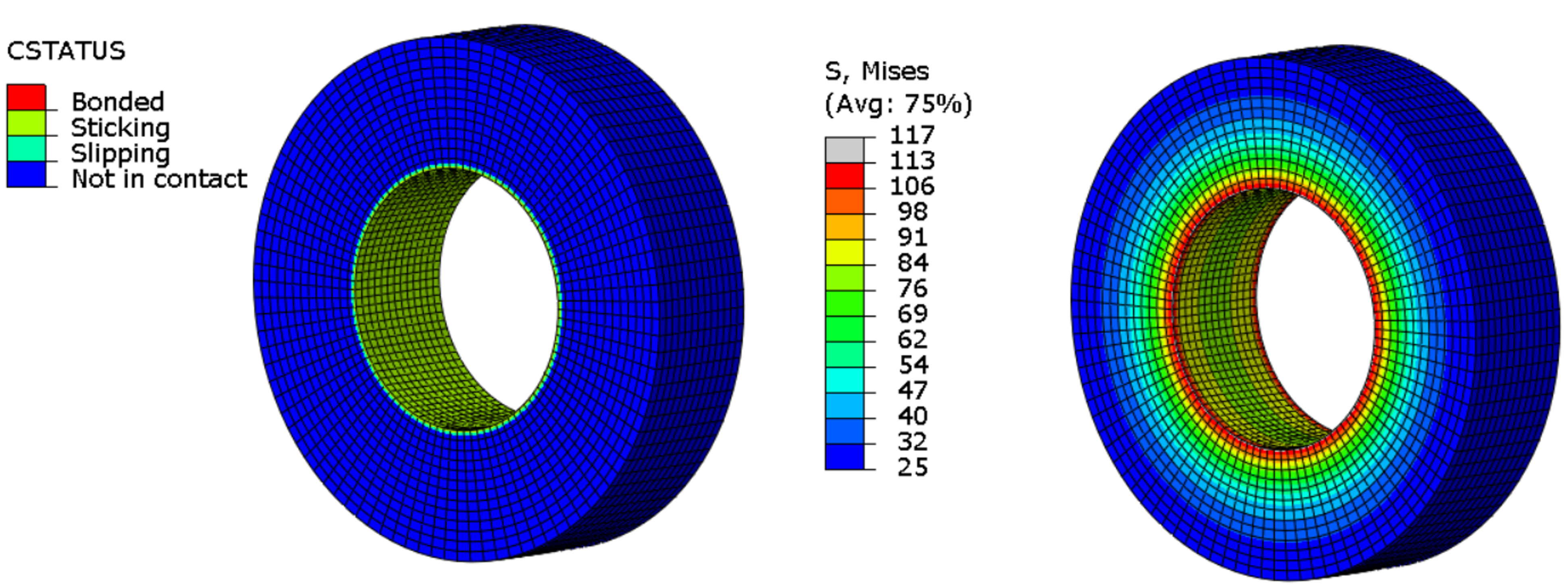
Contact status (left) and equivalent stresses (right) in step 2 ( cooling down)
In this example, the results of the different approaches are identical. The effort is similar for all variants. However, in the case of other geometries or even other real process flows, it may be better to keep the simulation as close to reality as possible. Then the latter method via heating would certainly be better.


