This is the reproduction of the extended abstract of the K-Day 2023 in Bayreuth.
Additively manufactured components are used in a wide range of applications and are made from a wide variety of materials.
In order not to miss out on this development, the software manufacturers of finite element systems have invested heavily in enabling the simulation of additive manufacturing with minimal user effort.
One challenge, for example, is the activation of elements as a function of time and space, including the heat transfer that occurs.
After a brief insight into the state of the art in the literature, this article will use a simple example to illustrate the process preparation and simulation of additive manufacturing.
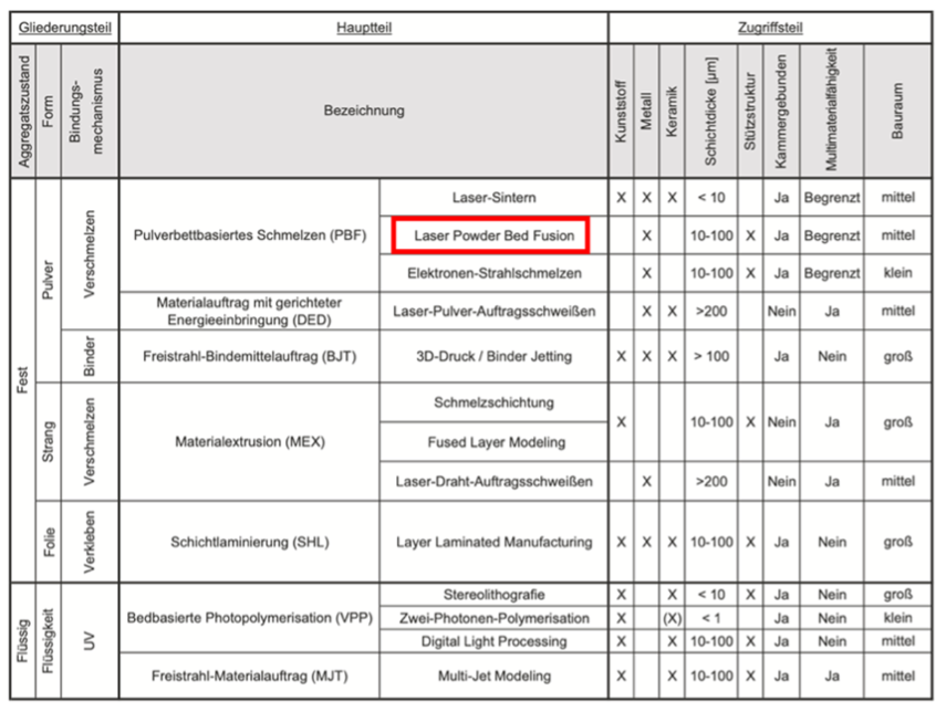
The process overview in [1] starts with the aggregate state, see the following figure.
In this article, we will focus on the laser powder bed process.
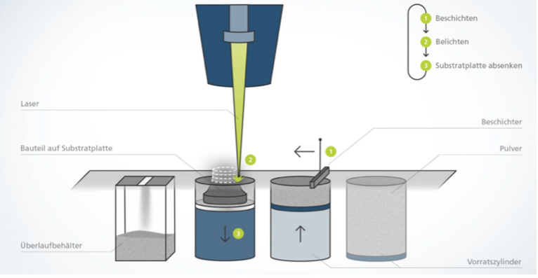
In this process, a thin layer of metal powder is spread on a table using a coater (see the following image from [2]) and then exposed by a laser.
The table is then lowered and another layer of powder is applied, which is exposed again.
Based on the literature cited so far, the process is also referred to as laser metal fusion (LMF) or powder bed-based laser melting or selective laser melting (SLM).
The unexposed powder must then be removed.
The powder is produced from a melt by means of gas atomization, see also [3].
The requirements for the process are manifold.
According to [1], the following are particularly important:
- Heating the building platform (table) to reduce residual stresses
- Heating installation space
- Protective gas against oxidation
- Imaging accuracy and layer thickness
- Surface roughness as a function of up and down skin angles
- Support structures
- Heat-affected zone
- Overlapping laser guidance
- Conversion errors (e.g. no acute angles)
- Laser diameter > minimum wall thickness.
According to [1], the following different approaches are used to simulate additive manufacturing:
- Permanent stretching method
- Sequentially coupled thermal-mechanical simulation
- Multi-scale approaches with micro and meso levels.
In this article, we limit ourselves to sequentially coupled thermal-mechanical finite element simulation.
During additive manufacturing, phase transitions and microstructural changes occur in metals depending on the temperature, time and location.
According to [4], particular attention must be paid to this:
- Different time scales between melting/solidification in milliseconds and component production in minutes and hours
- Different length scales, in micrometers of the local melt and the size of the component in hundreds of millimeters
- High temperature gradients around the melting area, which can lead to an anisotropic material.
The objectives of the simulation can be derived from the literature as follows:
- Component distortion due to residual stresses caused by cooling
- Component distortion due to residual stresses after removal of the support structures
- Microstructure and material properties.
Here, the use of larger time steps and coarse discretizations of the finite element mesh seems to be common.
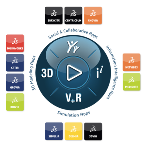
With 3DEXPERIENCE, Dassault Systèmes provides a platform for digital product development, see [5].
A key element is the compass, see image.
The various brands provide apps that are assigned to user roles.
The DELMIA and SIMULIA brands from the quadrant for simulation apps are essential for the applications shown here.
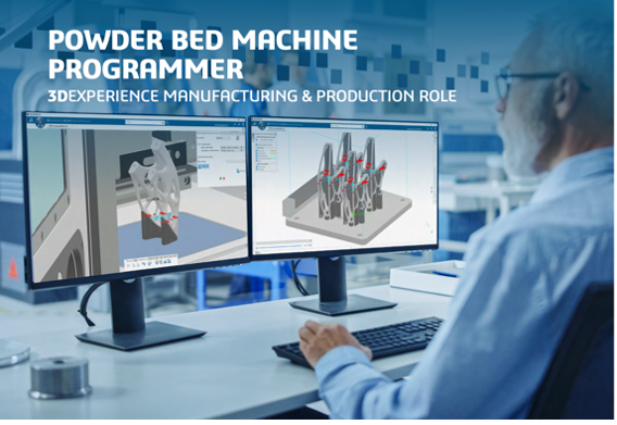
Here, the ‘Powder Bed Machine Programmer’ role with the ‘Powder Bed Fabrication’ app is used to set up the process and the ‘Additive Manufacturing Analysis Engineer’ role with the ‘Additive Manufacturing Scenario Creation’ app is used for the simulation.
We assume here that the component to be produced has already been created as CAD.
The example is based on a training example from Dassault Systèmes.
Guided processing sequences are a key feature of the 3DEXPERIENCE platform.
These have the great advantage of a guided, structured procedure.
However, the platform allows manual intervention beyond this guidance at any time.
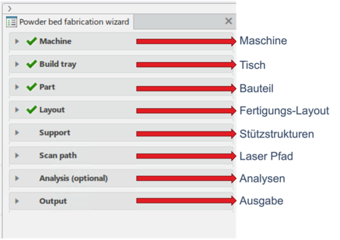
If you open the ‘Powder Bed Fabrication’ app, a wizard opens, here called ‘Powder bed fabrication wizard’.
In this article, we want to limit ourselves to a few points.
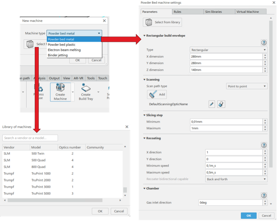
You start with the machine.
After selecting the process, you can create a generic machine or select a machine from a manufacturer stored in the system, see image.
Various definitions, e.g. for the installation space, the scanner and the shielding gas, are created or reused.
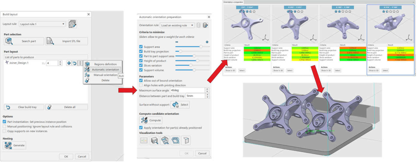
Once you have defined the table and selected the component, you are taken to the production layout.
As with many other work steps, it is also possible to use automatic or manual ways of definition.
Once you have defined how many components are to be produced on the table, a selection of key parameters opens when using automatic orientation, see the following image.
Here you can select specifications and weight them using a slider.
Four suggestions are then presented, which also highlight the respective weightings in color.
The user now selects a proposal.
Support structures are often required during production, e.g. to prevent movement of components in production.
Here too, the wizard supports the definition of these support structures.
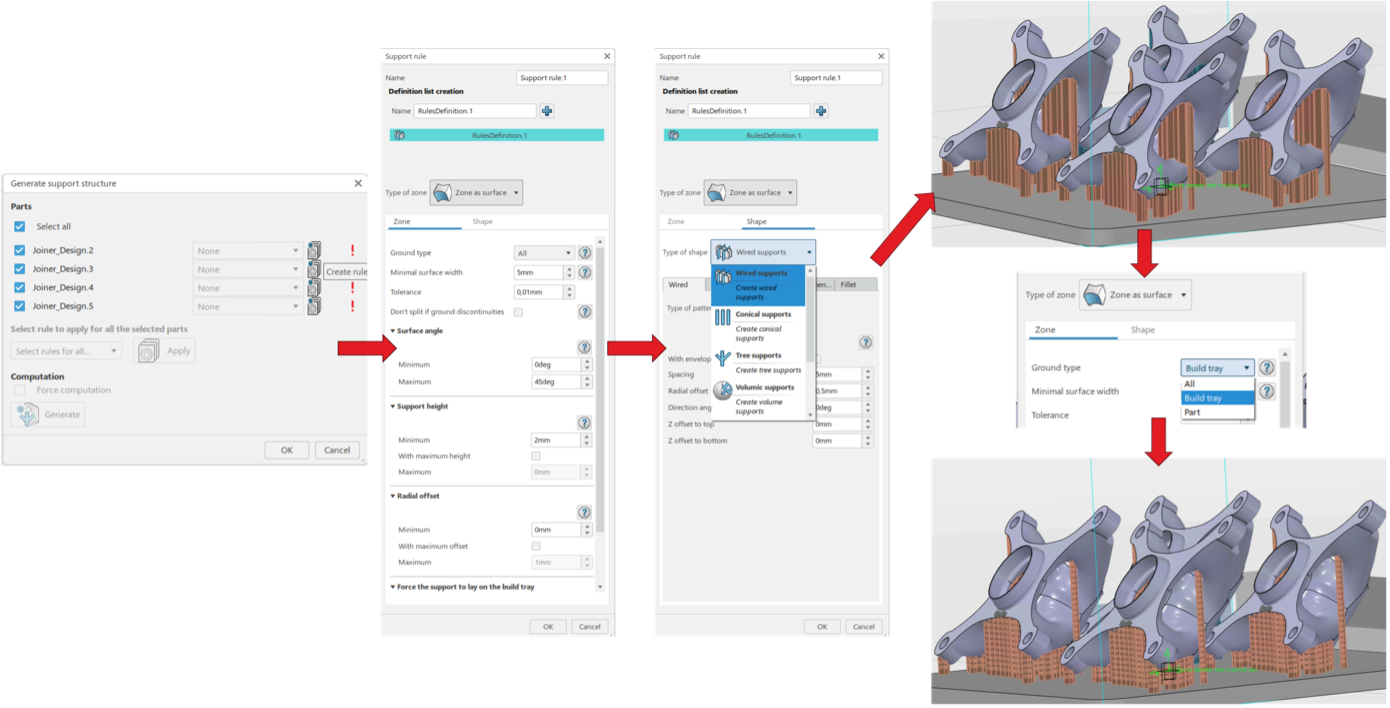
Rules are defined first, whereby different rules can also be defined for the individual components.
Geometric specifications such as width, angle or minimum height are set for the creation.
It is important to specify how the support structures are defined on the component and where they may be supported.
In the following image, flat support structures are first created with the ground type ‘All’ and then reset to ‘Build Tray’ (table).
The user can intervene manually and remove individual supports again, for example.
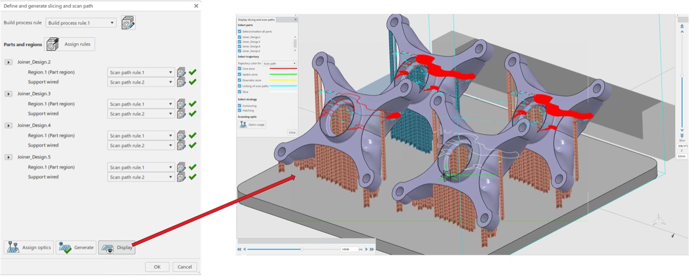
There are also many options for defining and controlling the slicing and scan paths.
The layers in which work is carried out and the path of the scanner in each layer are defined here, see image below.
Different rules, which were previously defined for the machine, can be used for the individual components and for the support structures.
The scanning process can then be displayed as a function of layer and time.
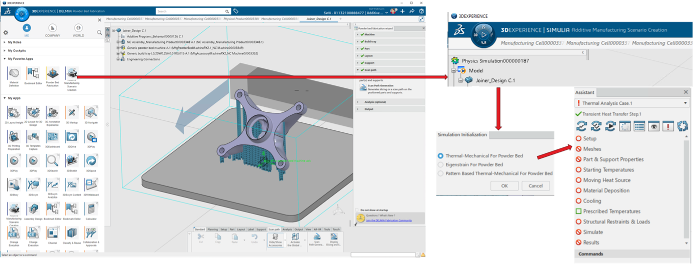
Once you have run through the wizard, the process is defined.
You can now export the process data for a machine or switch to simulation.
We limit ourselves to the simulation of the production of only one component.
We assume that the simultaneous production of four components has no influence on the production of a single component.
However, this need not be the case.
A major advantage of the 3DEXPERIENCE platform is its data consistency. Switching from the process definition to the simulation is very simple. You change the app and all previous definitions are automatically adopted if necessary, see the following image. The simulation type is required for initialization. As described above, we want to carry out a sequential thermal-mechanical coupled analysis. This time, the wizard for the process also run here is simply called ‘Assistent’.
Essential definitions have already been made, simulation models for the thermal simulation and for the mechanical simulation have already been created automatically with pre-set parameters.
In the background, the simulation uses a method for progressive activation of the elements analogous to the moving heat source (laser beam).
This activates strain and stress calculations as well as heat transfer via the material and the new surfaces.
Running through the wizard is quite simple due to the high level of automation.
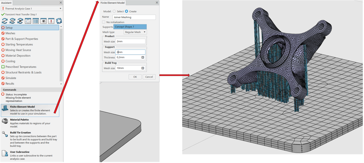
The wizard offers meshing, material definition and the connection of the individual components under Setup.
The mesh edge lengths can be defined during meshing, see the following image.
The wizard automatically selects the correct element types for the volumes of the component and the table as well as for the flat structure of the supports.
The following points of the wizard are quite easy to run through due to the high degree of pre-definition.
The starting temperatures are important for the thermal simulation.
A melting temperature is also requested here, which corresponds to the starting temperature of the activated elements.
However, this is more of a numerical value, which can be significantly below the physical melting temperature.
We will discuss the influence of the melting temperature on the simulation in a later article.
As examples of the high degree of automation, we show in the next picture from left to right the selection of the start temperatures, the material deposit and the heat dissipation.
This means that the selection of affected components is always pre-set.
The deformation of the previously activated elements (‘Follow deformation’) can be taken into account during material placement.
This can significantly improve the convergence of the simulation.
The values for heat dissipation are essentially based on empirical values, as the activated structures are encased in a metal powder in the real process.
Mechanical boundary conditions are required for the mechanical simulation with the procedure of non-linear statics.
Guided by the wizard, the weight force for all components, on the left in the following image, and the clamping of the underside of the table, in the center of the image, are defined.
A special feature is the manual clamping of all rotational degrees of freedom of the support structures, on the right of the image.
For numerical reasons, this is only necessary here for shell elements
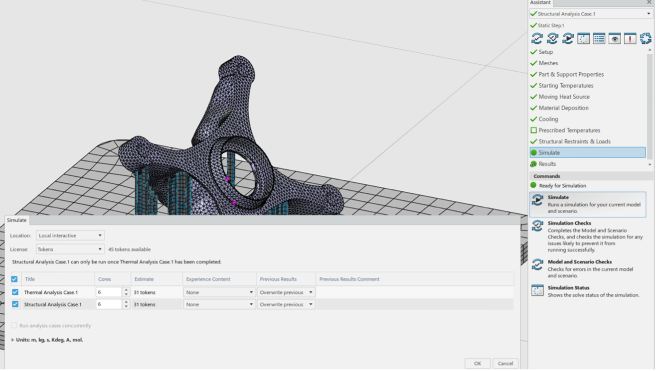
Once the wizard has been run, the simulation can be started.
The user can decide whether the simulation data should be stored locally or in the cloud and whether the simulations should be carried out locally or in the cloud, on how many cores and with which licenses.
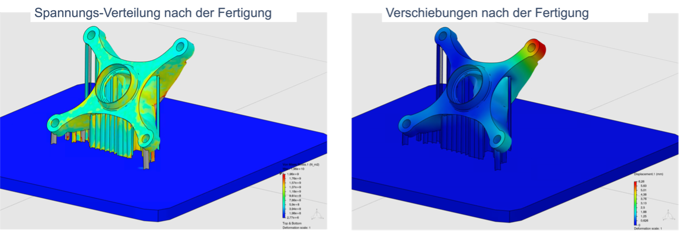
After the simulation, the results are analyzed.
The stress distribution and displacements after production are shown here as examples.
There are many examples of additive manufacturing simulation in the literature.
Simplified methods are often used here for time reasons.
In this article, we have shown how the manufacturing process is defined in the 3DEXPERIENCE platform.
Essential information for a later simulation, such as the temporal and spatial course of the exposure by a scanner, is defined and automatically transferred to the simulation.
Both the definition of the process and the setup of the simulation are guided by a wizard, which significantly reduces the effort and complexity of the task.
The sequential thermal-mechanical coupled analysis was demonstrated.
This is also a simplification, as time and space are resolved more macroscopically.
Further work is required, such as the comparison of simulation and real component production, in order to be able to make statements about the sensible use of simulation in additive manufacturing.
In part, this text and illustrations shown are based on research of evaluated literature. If this is the case, the sources are marked in the text by a number, e.g. [2], and the source is listed here. In part, however, the sources listed here should simply be understood as recommendations for further reading.
[1] Lachmayer, R., Ehlers, T., and Lippert, R. B., 2022, Entwicklungsmethodik für die Additive Fertigung, Springer Berlin Heidelberg, Berlin, Heidelberg.
[2] “Like a phoenix from the ashes”[Online] [Accessed: 29-Aug-2023].
[3] Höfemann, M., Schmale, H. C., Epperlein, L., Heemann, L., Mostaghimi, F., Schob, B., Zapf, H., Mahr, J., Paul, C., Höfner, L., and Fischer-Buehner, J., 2020, “A low-alloy steel material for laser additive manufacturing – process chain and properties,” Design for Additive Manufacturing 2019, R. Lachmayer, K. Rettschlag, and S. Kaierle, eds, Springer Berlin Heidelberg, Berlin, Heidelberg, pp. 29-41.
[4] Xie, J., Oancea, V., and Hurtado, J. A., “Phase Transformations in Metals during Additive Manufacturing Processes.”
[5] “We Are the 3DEXPERIENCE Company | Dassault Systèmes”[Online] [Accessed: 20-Jul-2023].
