For shaft systems with constant or changing cross-sections, a beam model can achieve a considerable reduction in the computational effort. In addition, such a simplified model can be easily incorporated into an assembly and modified with very little effort. In the following article it will be shown how the conversion of the solid model to the beam model can be performed quickly and efficiently. This is a hollow shaft with different cross sections and a length of 1670 mm.
The surfaces in the x-y plane will be selected. Für den Fall, dass diese noch nicht vorhanden sind, muss das zuerst partitioniert werden.
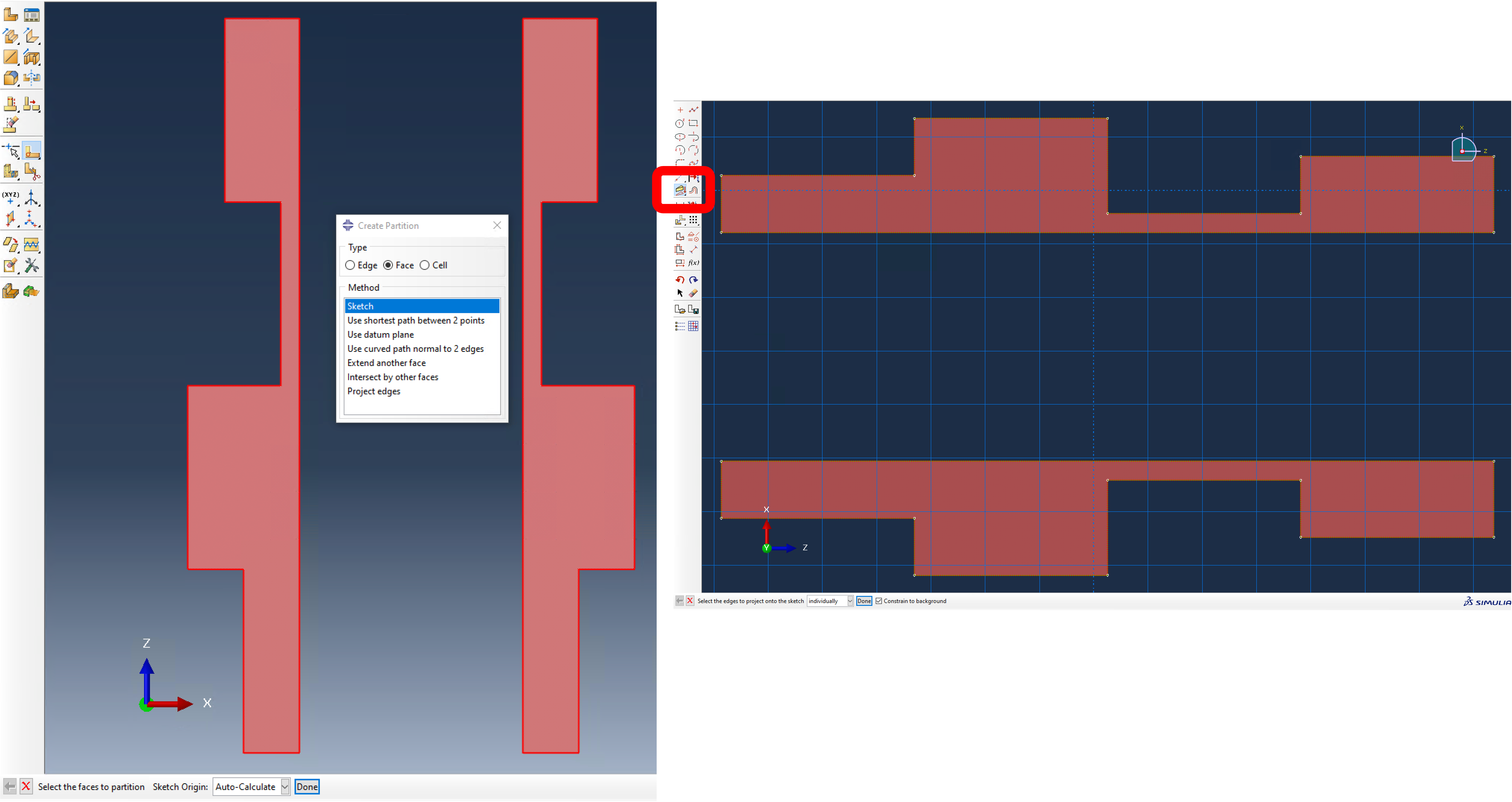
A pseudo-partition is created so that the contour of the profile can be saved as a sketch. (see picture).
Important here: The surfaces must be in the front view to avoid distortion.
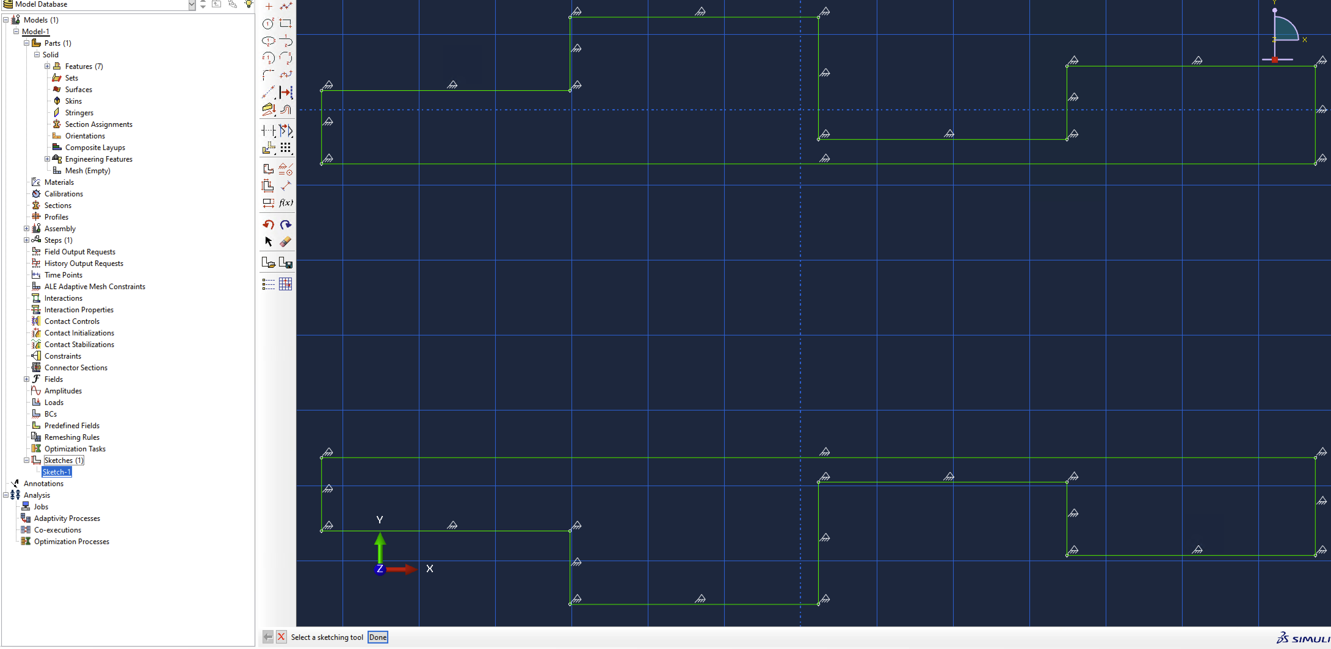
The sketch is now saved in the Sketcher and is subsequently available for reference.
A detailed explanation can be found at the end of the article under point 7 Worth knowing.
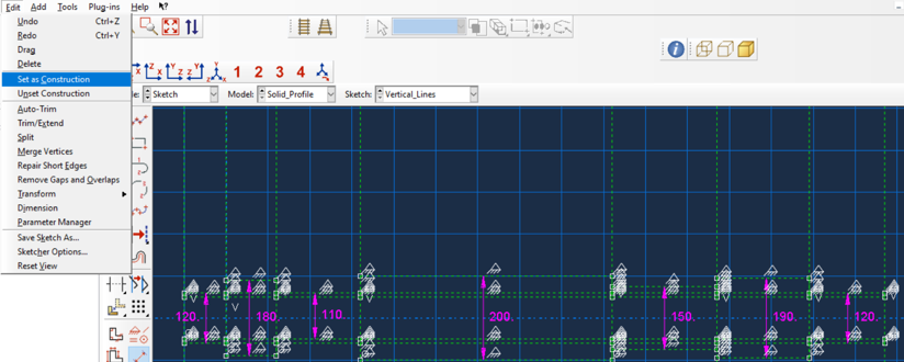
Via Sketches/Edit (quite far down in the model tree) I get into the editing of the created sketch. First, the lines of the sketch are projected into the drawing plane. Then the lines of the sketches are converted to the type “Construction”. Vertical guides are then created at the profile transitions. The diameters are then dimensioned.
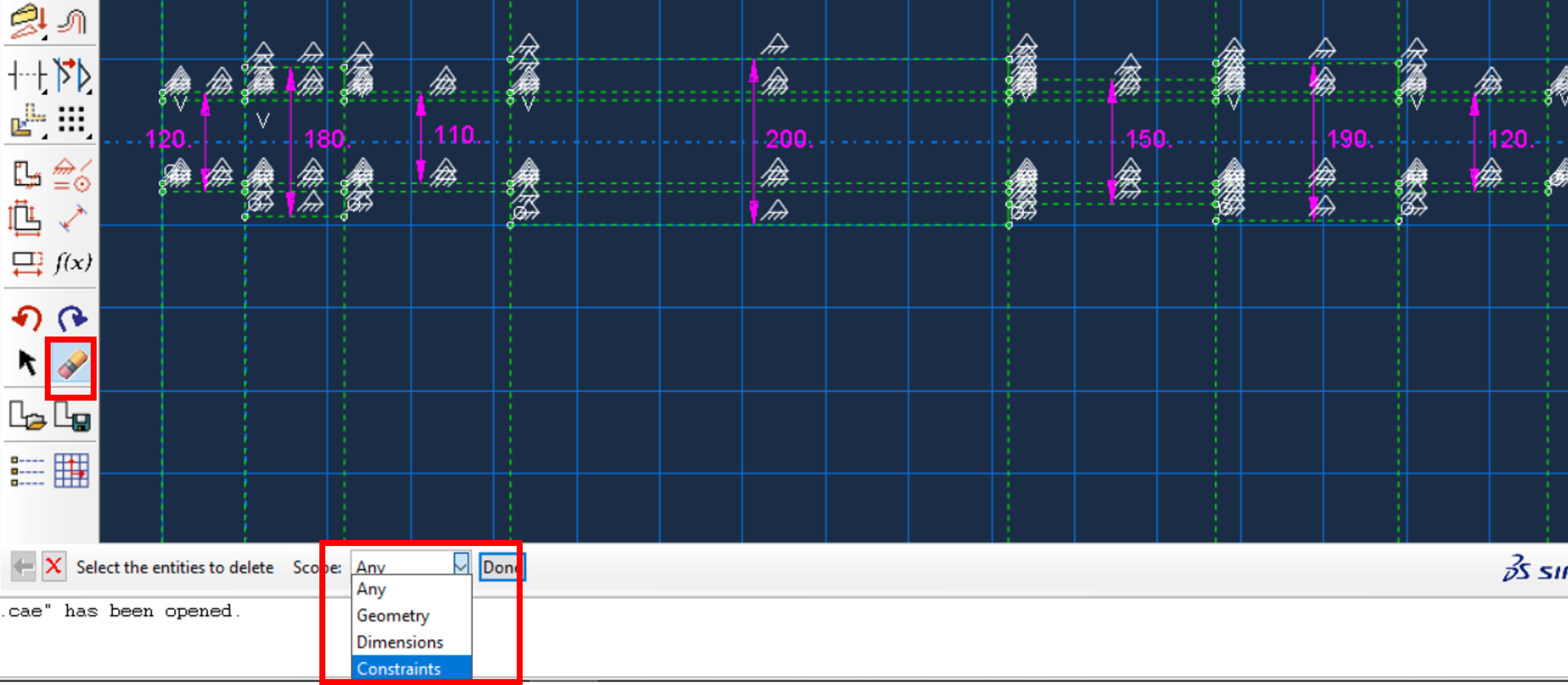
After dimensioning, the sketch is overdefined. This can be solved by deleting the constraints.
Once the constraints are removed, the sketch is ready and can be used later to create the beam. Note that the sketch contains the correct dimensions. The sketch should be saved under a unique name.
In addition, a screenshot of the sketch should be made and cropped with a suitable image editing program so that only the profile with the dimensions is visible.
This image can be used later in the Property module to easily assign the profiles. The finished sketch will look like this :
Now the beam can be created as a “Wire, 3D” part using the sketch.
For this purpose, a line is created from profile to profile, central red line in the picture below. Thus, partitioning is no longer necessary and all profiles have the correct length.
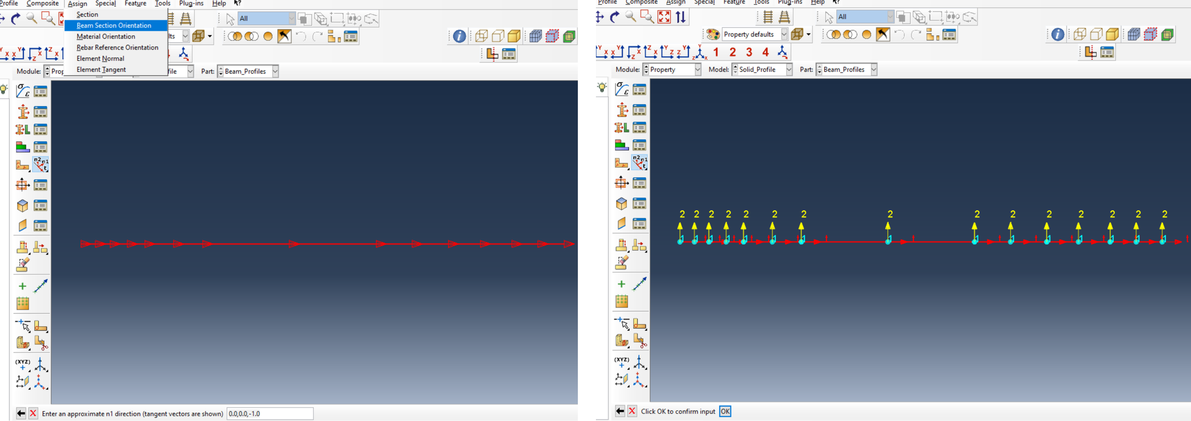
The next step is to define the orientation of the beam.
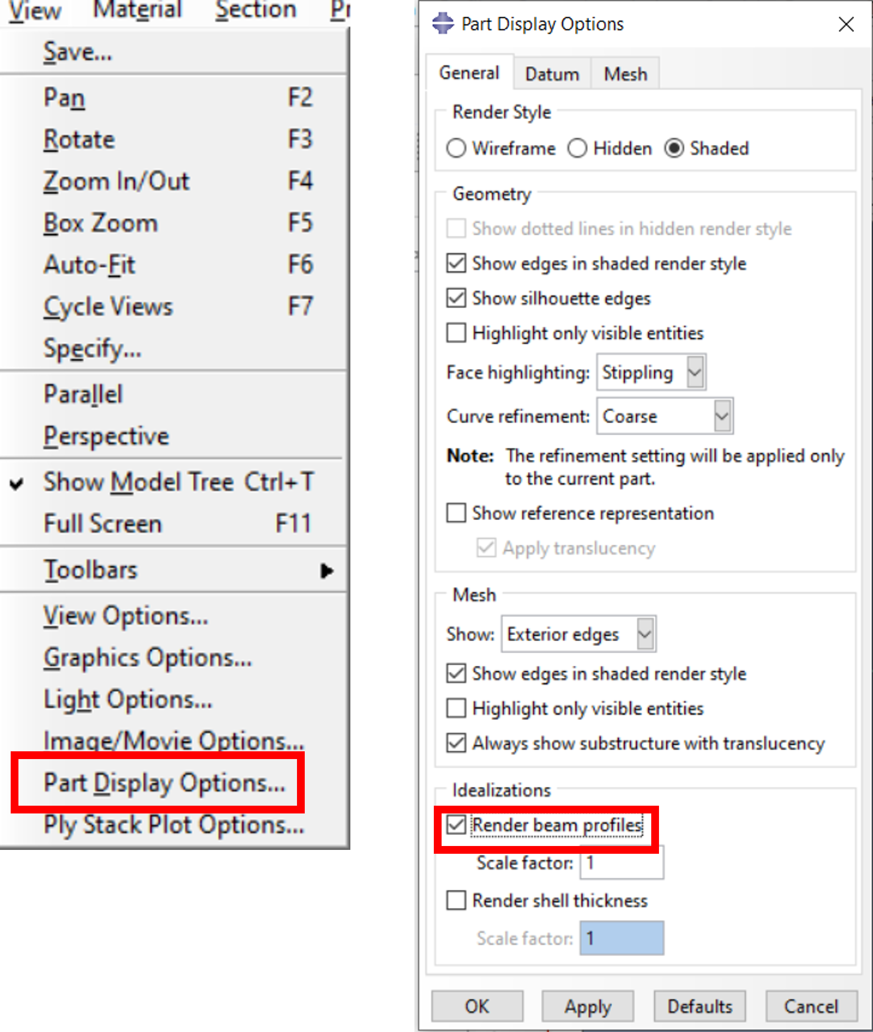
Now the display of the beam profile is set.
This is essential for the following procedure.
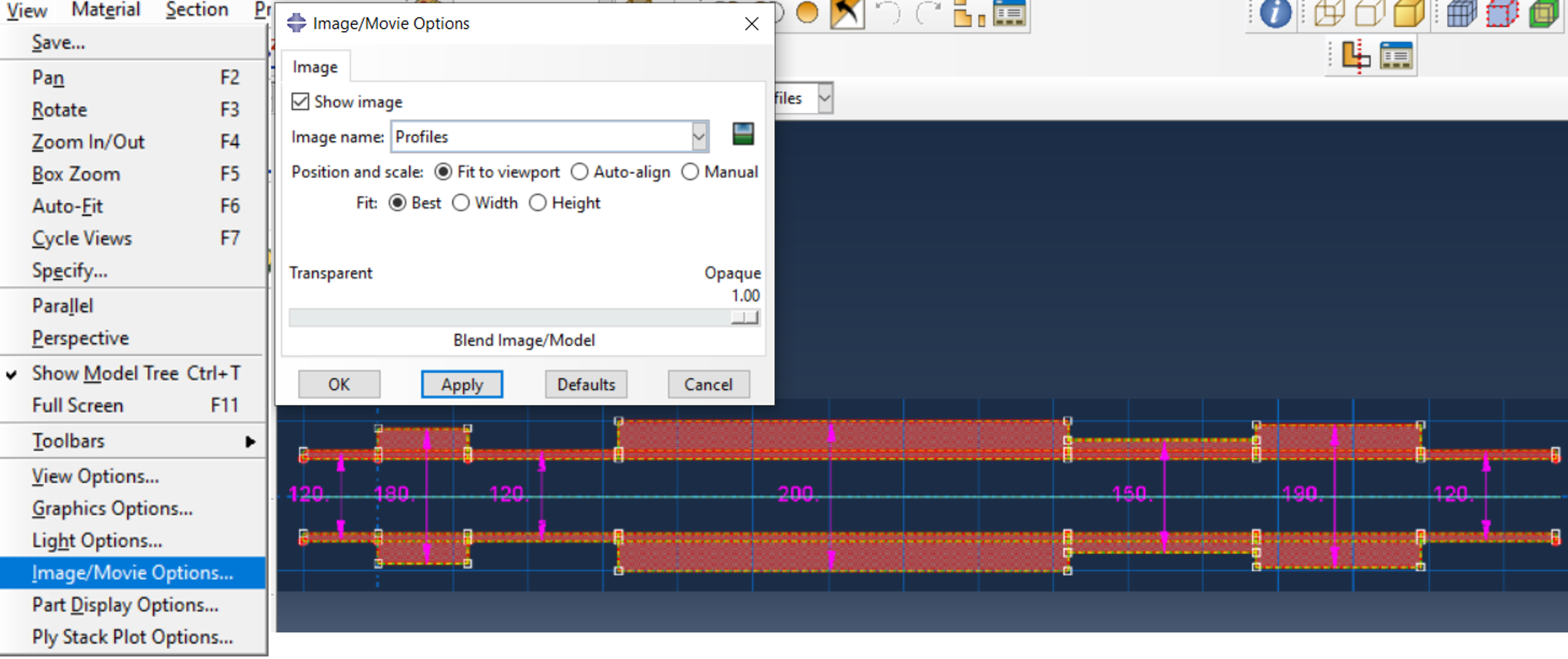
Before the profiles and the corresponding sections are created in the Property module, the previously created screenshot is first loaded into the viewport – via View/Image Movie Options as shown in the image below. Here the screenshot contains the dimensioned inner surfaces. The display can be switched on/off and the position can be changed.
This offers the great advantage that the required profiles are easily recognizable and no dimensions have to be tapped from the solid model.
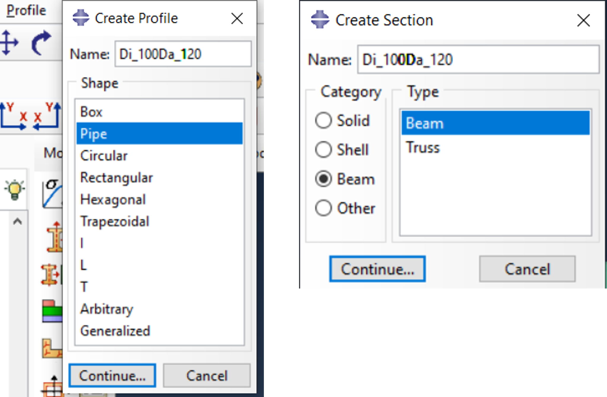
All profiles and their sections are now defined. It is also recommended to use unique geometry-related names and to adapt the section names to the profile names.
The part can now be adjusted to the sketch with high accuracy by only holding the “ALT” key while zooming and moving !!!!. Then the required sections can be assigned effortlessly.
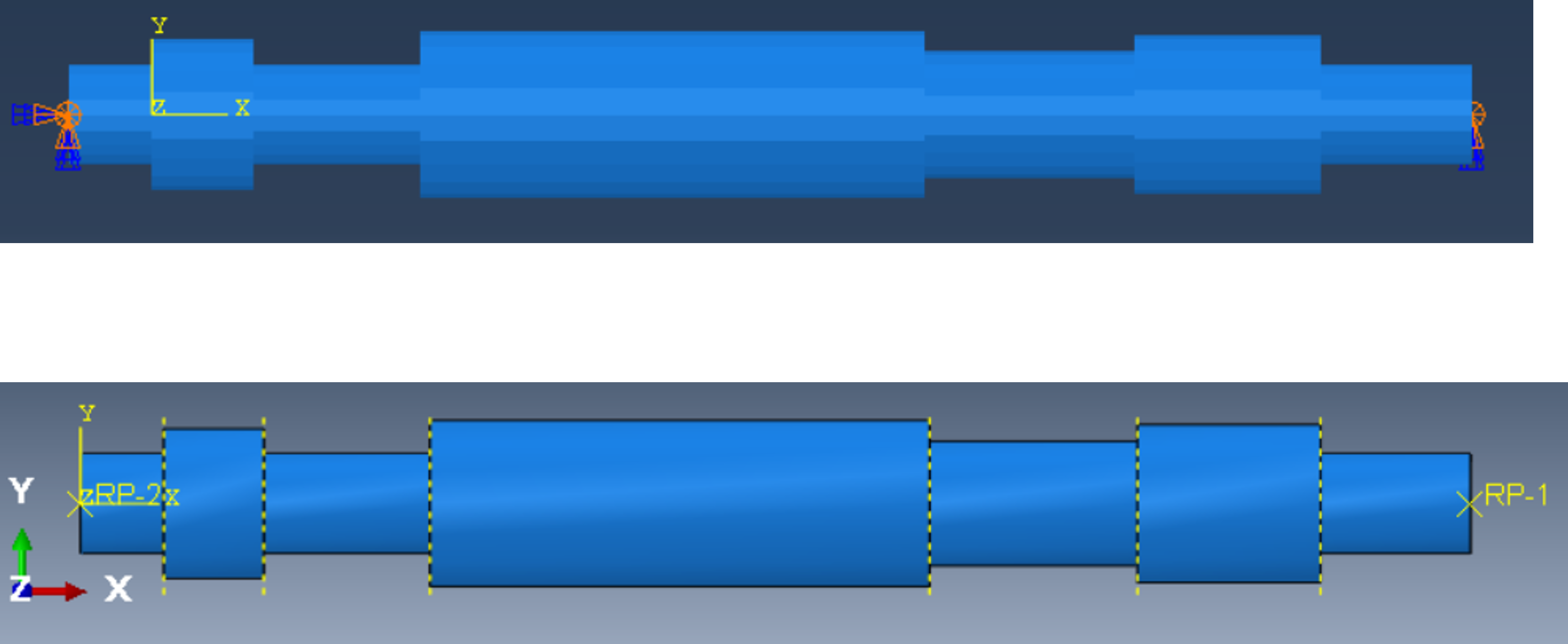
A simple modal analysis serves as an example for the comparison of the simulation with beam model (upper drawing below) and solid model (lower drawing below) with beam elements type B31 and solid elements type C3D8I. Here, the degrees of freedom of both models are clamped at the ends except for the UR3. For clamping to the solid model, the nodes at the ends are kinematically coupled to a reference point via node coupling. Make sure that the reference points at each end are centered in the cross section.
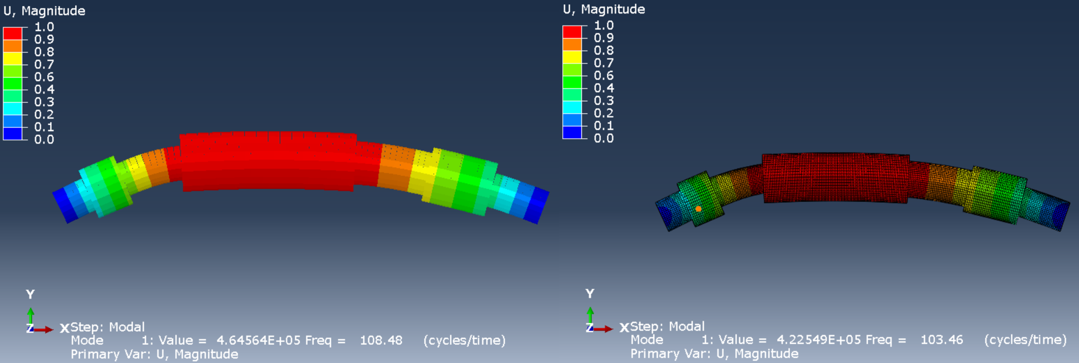
The first eigenmode of the modal analysis is 108.48 Hz for the beam model (left in the image below) and 103.46 Hz for the solid model (right in the image below). The differences result from the different consideration of the changes in the outer diameters.
To eliminate this influence, the calculation was performed again – but this time with constant diameters, inside 100 mm and outside 120 mm. The first eigenmode is now 106.63 Hz for the beam model (left in the picture below) and 106.65 Hz for the solid model (right in the picture below).
This paper is intended to give the user a procedure for easily creating a beam structure from a Solid CAD data. It is up to the user to judge whether the replacement model with beam meets his requirements.
The deviations in the modal analysis show that deviations of a few percent can quickly occur with shorter shafts, here 1670mm, and less slender beam profiles. In general, the longer the structure and the leaner its profiles, the smaller the deviations.
The use of the “correct” element types is an essential prerequisite for a predictive finite element simulation. We want to devote ourselves to this topic again and again. See also our article Element selection and discretization in Abaqus Unified FEA using the example of a linear load on a bending beam.
To create the sketch we use a little trick. As a starting position here will be an axially symmetric body. We have created this ourselves in the example here (Create Part/3D/Deformable/Solid Extrusion). The body has no partitions in the direction of the axis (here the z-axis), left in the picture below. We now create a layer (Tools/Datum/Plane 3points) which divides the body in the middle, right in the image below.
Now we want to select the surfaces in this plane. This can be done very easily if you restrict the Select Entities for a Replace Selected to the parts that are completely in the selection frame, left and center in the image below. As a result, you get the centered surfaces, right in the picture below.
The surfaces are now in the x-z plane, but this does not bother further.
Now the trick. We start a Create Partition/Face/Sketch and select the faces, left in the image below. Then Abaqus/CAE asks for the selection of an Edge vertical and on the right. This gives us the option to reposition the sketch in the layer, on the right side of the image below. The cut is supposedly still in the x-z plane. However, no Edges have been added to the sketch yet. We do this via Project Edges, in the red rectangle in the image below. We select everything.
The image changes, on the left side of the image below. Via Save sketch we can now save our sketch, centered in the image below. Now we finish the procedure with a determined click on the red cross, on the right side of the image below. The operation of a partition is lost, but we only wanted to create a sketch.
We have now created a sketch that we can continue to use as we wish.


