One goal of many simulations is to correctly calculate the stresses of the components under load. In one paper, Element Selection and Discretization in Abaqus, we have already looked at element selection and fineness of meshing. However, the calculated stresses also depend on the “correct” resolution of the component geometry. This is the topic we want to address in the following article.
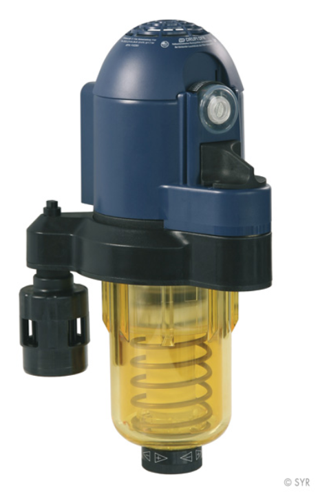
As an example, we use a filter cup, such as the one found on the web. We have taken the picture on the right from a website, [4]. The filter cup is the yellow component.
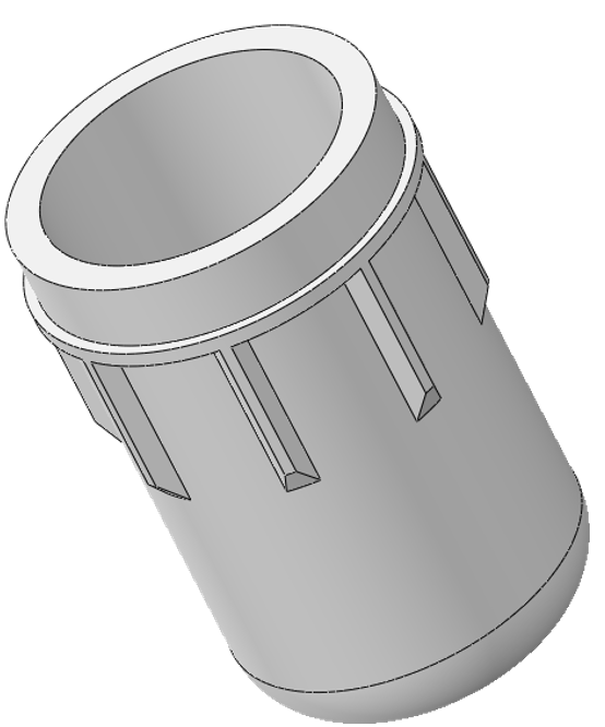
We have idealized the filter cup and built it as an Abaqus model.
Our idealized filter cup exhibits symmetries, on the left in the image below. We take advantage of these symmetries by using only a section of the model for the simulations, on the right in the image below.
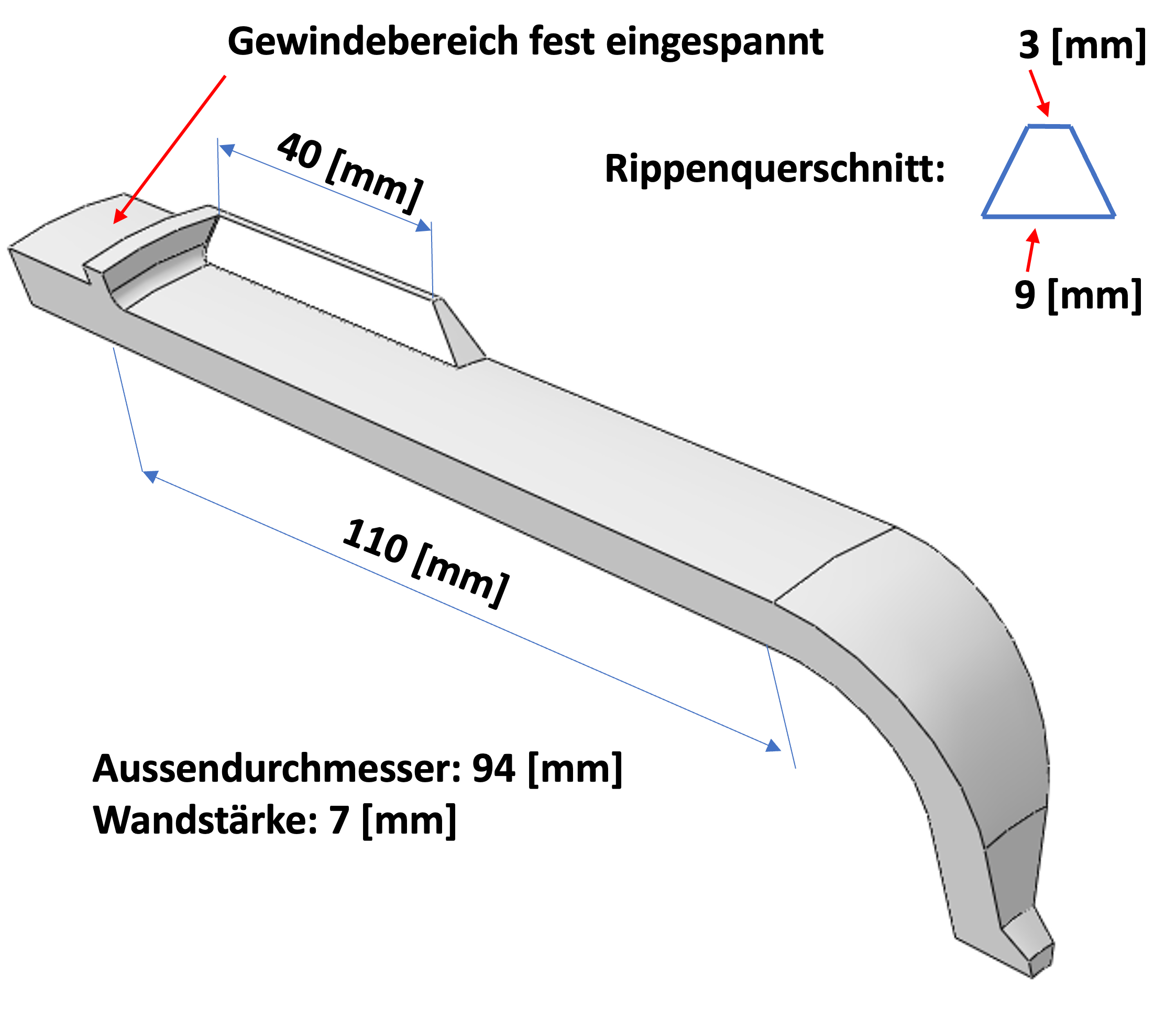
For the idealization of the filter cup we use the dimensions given in the picture below.
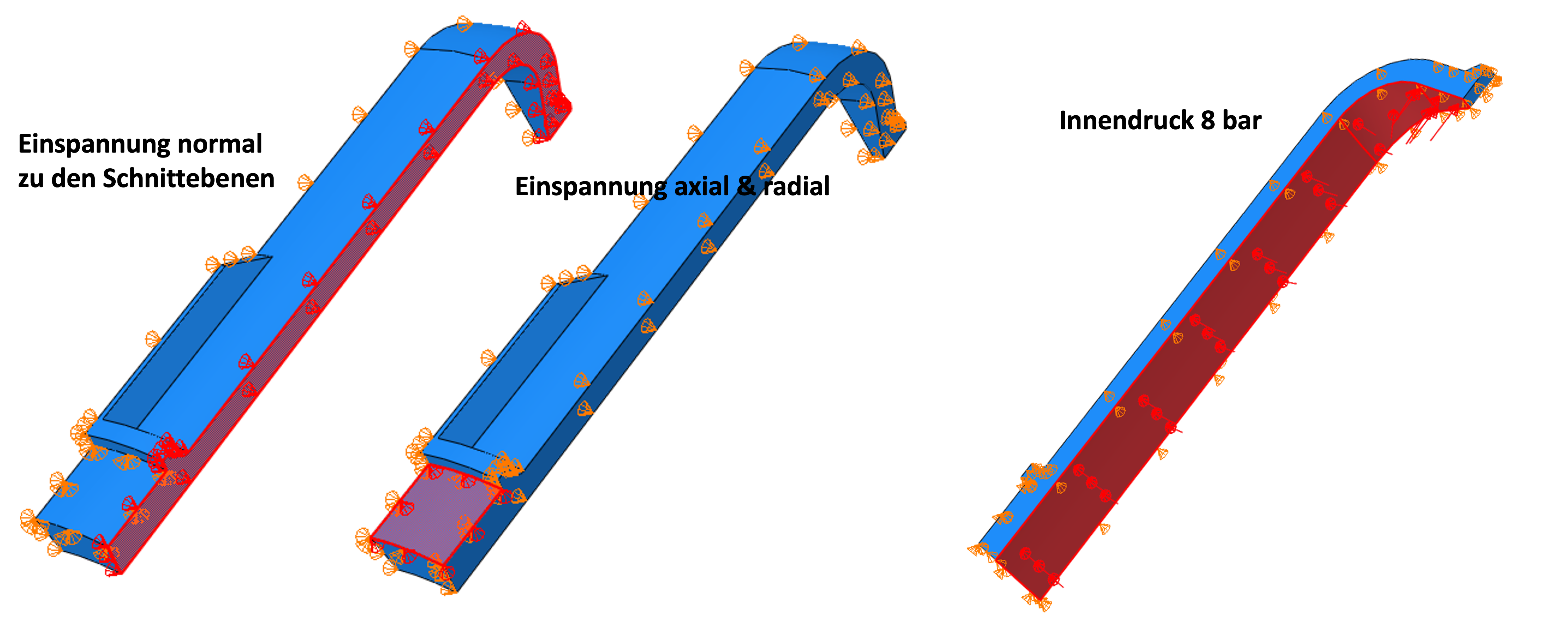
The boundary conditions (restraints) must be correctly defined on the cut surfaces. The boundary conditions for the nodes are defined by means of the transformation into a local coordinate system as described in [1|. In this case, a cylindrical coordinate system (radial R=x1, tangential θ=y1, axial Z=z1) was chosen and the surfaces were fixed in the circumferential direction. In addition, the upper edge, which is held by the thread, was clamped radially and axially. The used boundary conditions can be seen on the left in the picture below. We use an internal pressure of 8 bar as load, right in the picture below.
In this case, the radial restraints are equivalent to the use of a cyclic symmetry. A corresponding comparison is provided in the Worth Knowing section of this article.
Quadratic tetrahedra (C3D10) with a general element edge length of 2 mm were used for meshing. Critical areas expected in advance were not given separate attention, i.e., not finely meshed. Due to the geometry and without using partitions, meshing in Abaqus/CAE with (quadratic) tetrahedra is mandatory, see picture below.
The step used is a Static, General with NLGEOM=YES. The load is increased linearly over the load step up to the target value.
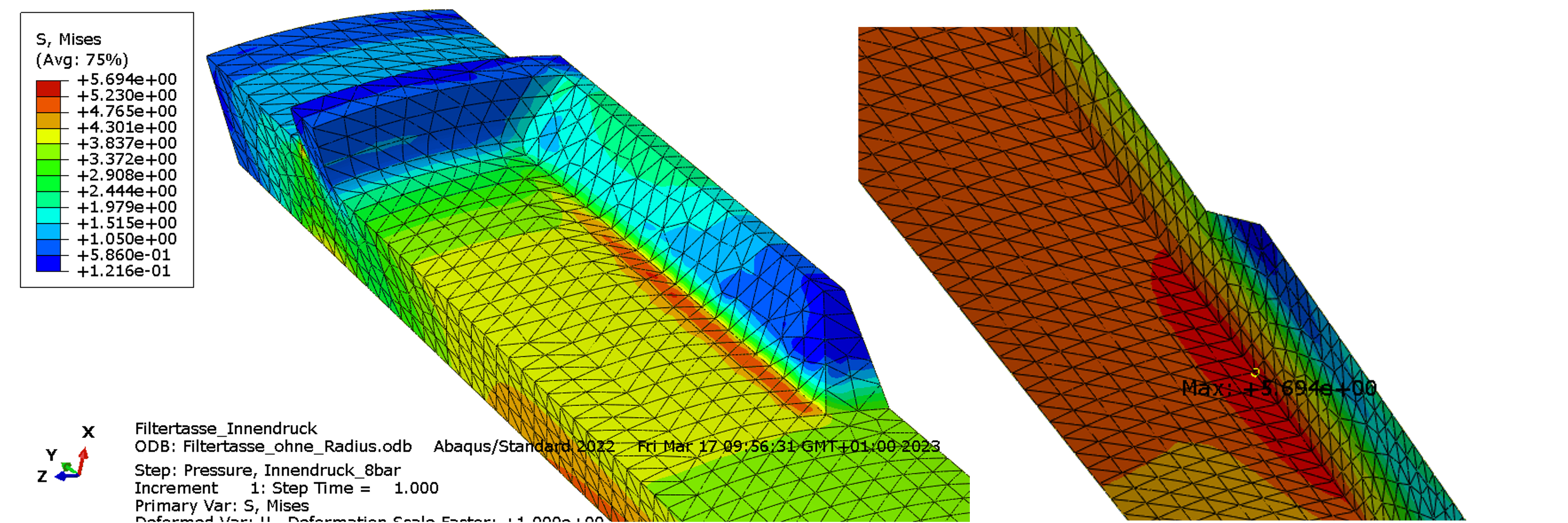
When the load is reached, the maximum equivalent stress (MISES) is 5.7 MPa, figure below. The stress maximum is located on the inside. At the base of the rib in the axial direction, a stress concentration is indicated, but it is slightly lower.
At this point, we could now end our work. However, we are curious and want to investigate the influence of a different resolution of the geometry at the axial rib. To do this, we vary our model in two steps. First, at the base of the rib, we place an element with a much smaller edge length normal to the rib. Second, we model a radius into the base of the rib.
In the first result, we noted a stress concentration at the base of the rib but not on the rib. According to the representation in the picture below, we vary the edge length of the elements that directly connect to the foot. To be able to change the lengths of the element edges locally, we have partitioned the cell in this area. First we use an edge length of 0.3 mm.
The equivalent stress on the inner side still shows 5.7 MPa. However, at the base of the rib, the stress now increases to 7.73 MPa, see picture below. Consequently, the stress maximum is no longer located on the inside.
In a next step we use an element edge length of 0.03 mm, left in the picture below. The maximum stress at the base of the rib now increases to 18.7 MPa, on the right in the picture below.
By simply varying the element edge length and thus improving the resolution of the rib-to-body transition, the stress maximum shifts from the inside to the base of the rib on the outside. In addition, the maximum increases significantly as a function of the element edge length.
Transitions with an sharp edge are rather rare in mechanical engineering. We therefore vary our model and use a radius in the transition from rib to outer surface. Here we keep the radius of 0.2 mm, see picture below, constant in the following calculations.
Using the edge in the radius, we vary the number of elements perpendicular to the rib. In the first case we use 2 elements. The maximum equivalent stress increases to 12.01 MPa, see figure below.
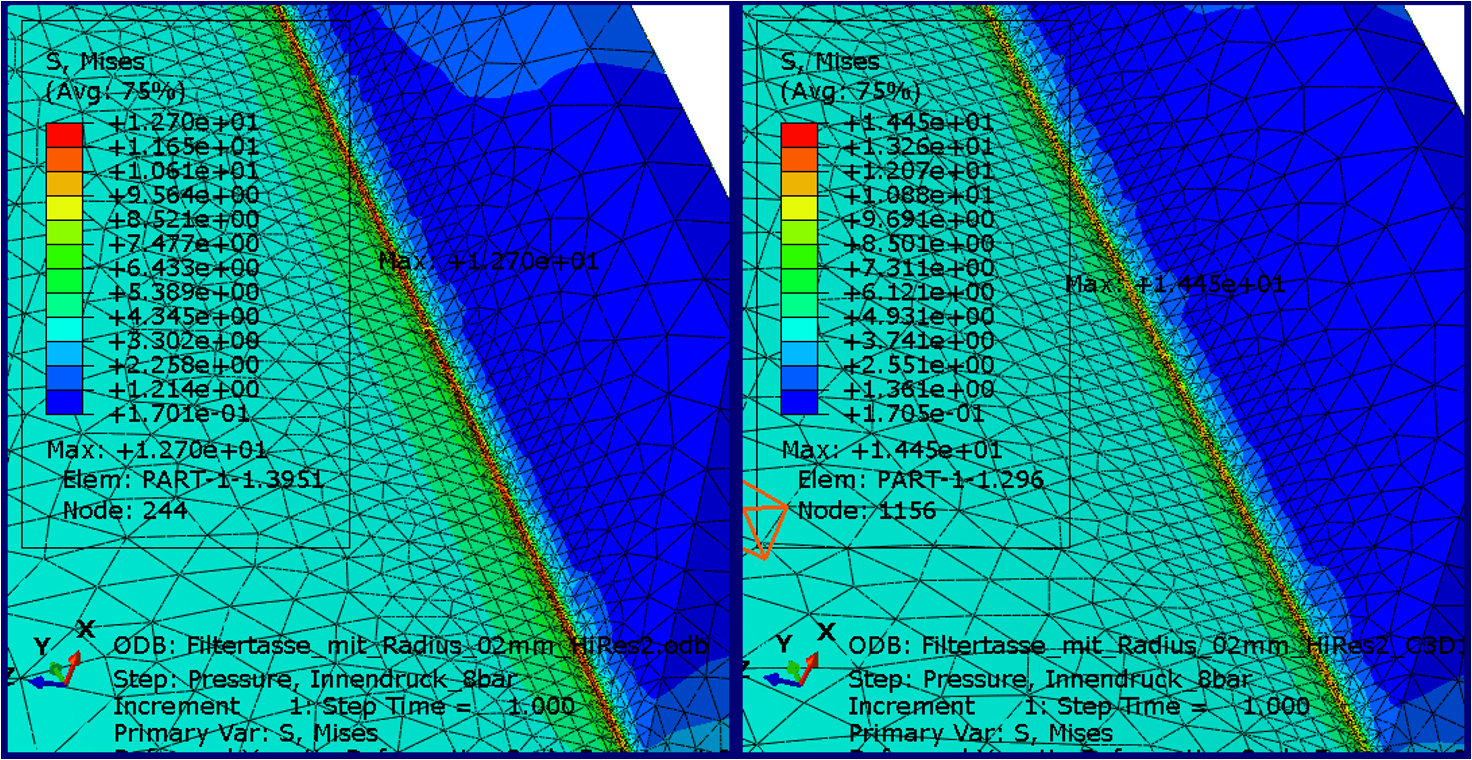
In the second case we use 4 elements. The maximum equivalent stress increases to 12.7 MPa (i.e. by almost 5%), see figure below.
Now we vary the element type used. For several years now, Abaqus Unified FEA provides solid elements with an improved surface stress description to the user. However, for tetrahedra these are only available together with the hybrid description (linear pressure) (C3D10HS), which can influence the result as well. The maximum stress increases again, now to 14.45 MPa, picture below.
The introduction of a radius leads to a significant increase in the maximum equivalent stress compared to the original solution. Also the variation of the element type with a better mapping of surface tensions leads to a different result.
The stresses occurring during loading are an essential measure for assessing the quality of a component. Using the simple example of a filter cup under internal pressure, we wanted to show that maximum equivalent stresses can vary quite significantly with different geometric resolution.
First, we use a quite plausible homogeneous mesh edge length of 2 mm. The maximum equivalent stress is found on the inside and is 5.7 MPa. We additionally detect a stress maximum at the base of the axial ribs on the outside. Using a finer mesh in this area and, alternatively, introducing a transition radius changes the results significantly. The maximum equivalent stresses are now in the transition area of the ribs and can reach higher values (up to 300%).
In addition to the fineness of the meshing and the choice of element, the resolution of the component geometry influences the result. The user is requested to observe these influencing variables. We are happy to provide support.
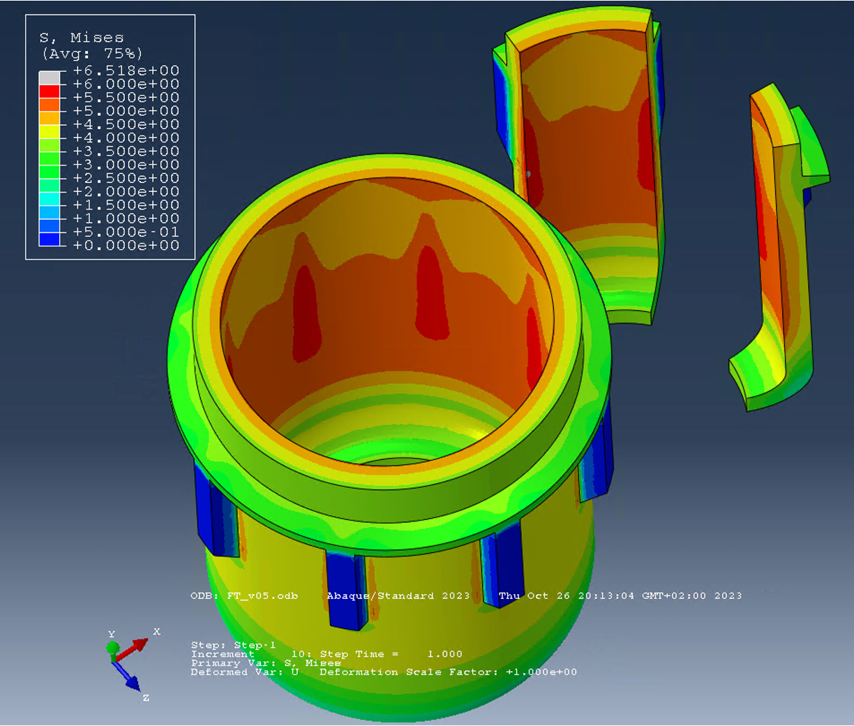
As described above, in this example we use symmetry about the axis of rotation to constrain the model size. As we described in the article Cyclic Symmetry in Abaqus FEA, the use of cyclic symmetry lends itself here. An advantage of using cyclic symmetry is the fact that the user does not have to worry about the boundary conditions in the circumferential direction. In this case, we decided otherwise. To prove that the different models are equivalent, we have created a corresponding example. In this example, we have compared a full model with a 1/8 model using cyclic symmetry and with 1/16 model like the one above. Also in this example we used square tetrahedra (C3D10) and the original homogeneous meshing. In the image below, you can see that all models deliver equivalent results.
Not equivalent is the numerical effort for the different models. In the image below we have compared the number of variables, the computation time and the required memory (RAM). It turns out that it can be worthwhile to use real symmetries in models. But please do this only if you are sure that the problem allows the use of symmetries.
Just briefly, let’s draw a comparison with the pressure vessel formula. Detailed explanations can be found in [3] and in German in [2]. In the above example, it is important to note that the ratio of diameter to wall thickness does not satisfy the conditions of the pressure vessel formula. The boundary conditions also do not correspond to those of a pressure vessel. Therefore, only the tangential stress can be compared well.
Using the above geometrical values with an average diameter dm=87 mm as well as a wall thickness of s=7 mm and a pressure of 0.8 MPa, the pressure vessel formula gives a tangential stress of 4.97 MPa, formula and figures from [2] in the figure below. This corresponds quite well to the values of the tangential stress in our example.
In part, this text and illustrations shown are based on research of evaluated literature. If this is the case, the sources are marked in the text by a number, e.g. [2], and the source is listed here.
In part, however, the sources listed here should simply be understood as recommendations for further reading.
