Simulation – i.e. the digital representation of the manufacture, use and operation of products in structural mechanics, fluid mechanics or electromagnetism – is of great importance in product development.
The use of simulation has been growing rapidly, especially in recent years.
A significant proportion of these simulations are carried out by specially trained calculation engineers.
In recent years, there has been growing criticism of the existing system of separating design and simulation.
Last year, the author presented various approaches to the democratization of simulation.
After a review of the presentation at the K-Day 2023, see also here or [1], the example of a supposedly simple problem shows that preliminary work is often necessary to ensure the quality of a simulation.
Looking at a few headlines about simulation these days, it is easy to get the impression that the immediate integration of simulation into existing development processes is necessary.
The following picture shows a few of these headlines.
According to [2], it is important that the “creative” construction process is not interrupted. In the past, this was done by waiting for tests or waiting for the simulation. In [3], the simulation department is described as a bottleneck in the development process.
In [4], the sequential workflow of design-simulation-design leads to ineffective development processes.
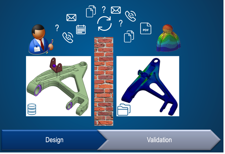
The term “working in silos” is often used. An internal Dassault Systèmes document illustrates this work in silos:
In recent years, the development of software systems for simulation has led to a significant improvement in simulation tools. The main points are:
- Improved geometry preparation
- Automatic meshing of even “bad” geometries
- Improved convergence behavior of the implicit solver
- Use of explicit solvers for static problems
- Use of automatic contact between components
- Elimination of interfaces for multi-physics applications.
In [3], the advantages of design-integrated simulation for industry are presented on the basis of survey results. A distinction is made between innovative leading companies (best-in-class) and the “rest” (all others). Emphasis is placed on “left shifting”, an early verification and optimization of the product, on the left in the following image. Many companies are striving to switch to design-integrated simulation, centered in the following image. This enabled the companies to significantly reduce the costs and duration of the development processes, pictured right.
According to [2], the use of simulation in the design process is particularly important because the change from an experience-based to a knowledge-based decision must take place in the design.
In [5] the advantages of a design-integrated simulation are presented. The demands on design processes have risen sharply in a more difficult environment. Here, design-integrated simulation is a problem solver and thus accelerates the democratization of simulation.
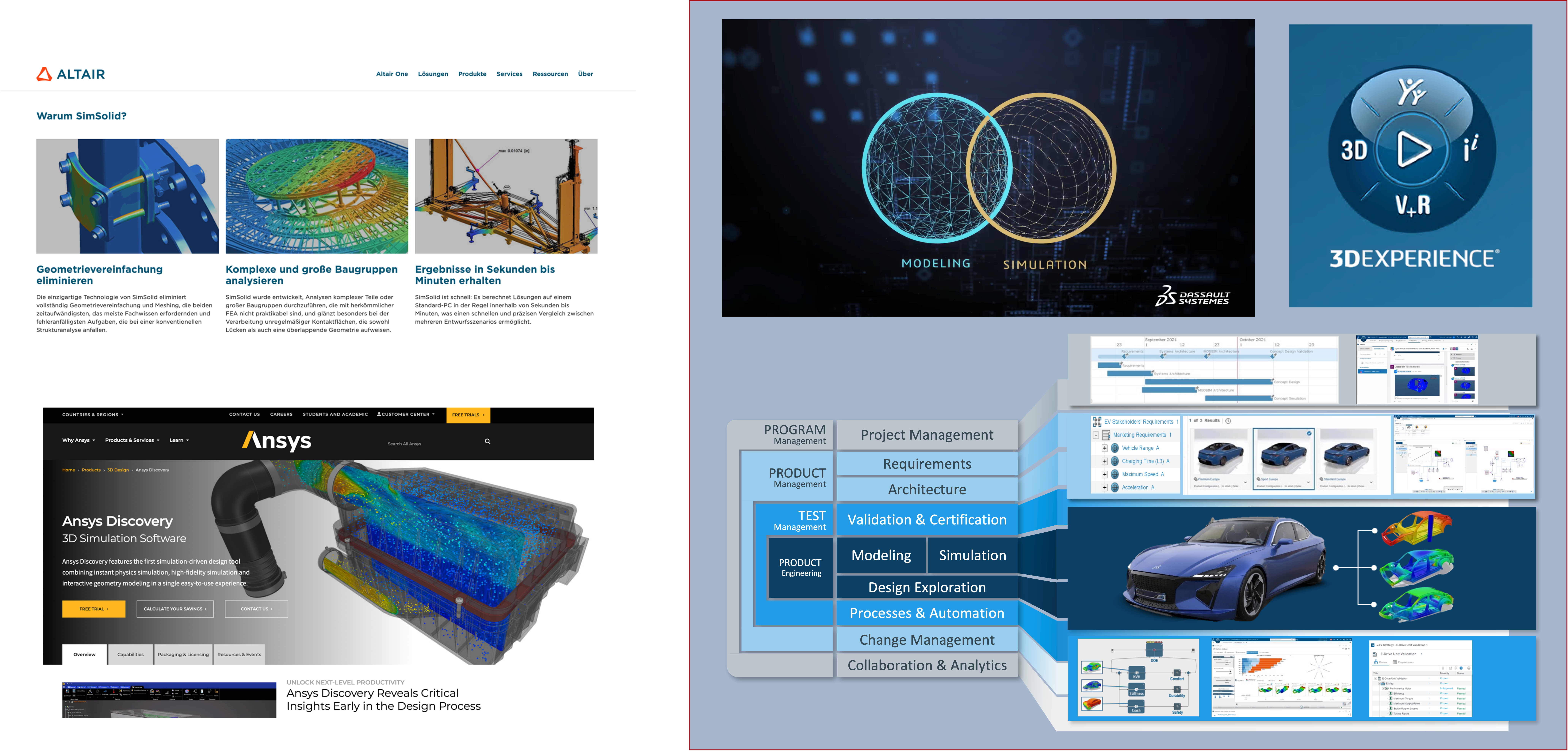
Today’s software systems offer corresponding solutions, see the following image.
In [6] describes the product SimSolid from the company Altair.
In [7] the ANSYS Discovery software is presented.
In [8] describes the MODSIM approach from Dassault Systèmes.
There are sufficient arguments in the literature for a significant strengthening of design-integrated simulation. The democratization of simulation leads to better products in shorter development processes. The software manufacturers provide the necessary tools for this, whereby a distinction can be made between guided and newer/automated calculation processes.
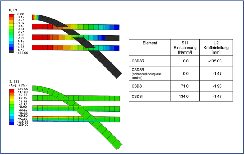
If you ask an experienced calculation engineer, there is a high probability that he will have strong reservations about this development. On our website [9], also here, we have an article that deals with the right choice of elements for a simulation. The linear load on a bending beam serves as an example. This shows that the wrong choice of element and discretization can lead to completely wrong results. In the following image, only the selection of one element, which is rarely used in practice, leads to the correct result.
In the literature on automated calculation processes, there are references to the use of reference memory (Reference Memory in [10]), the fidelity or the memory of the graphics card to increase the quality of the calculation [2].
This appears to be rather difficult, as no literature has yet been found that defines the dependency of the physics of a simulation on such variables in more detail.
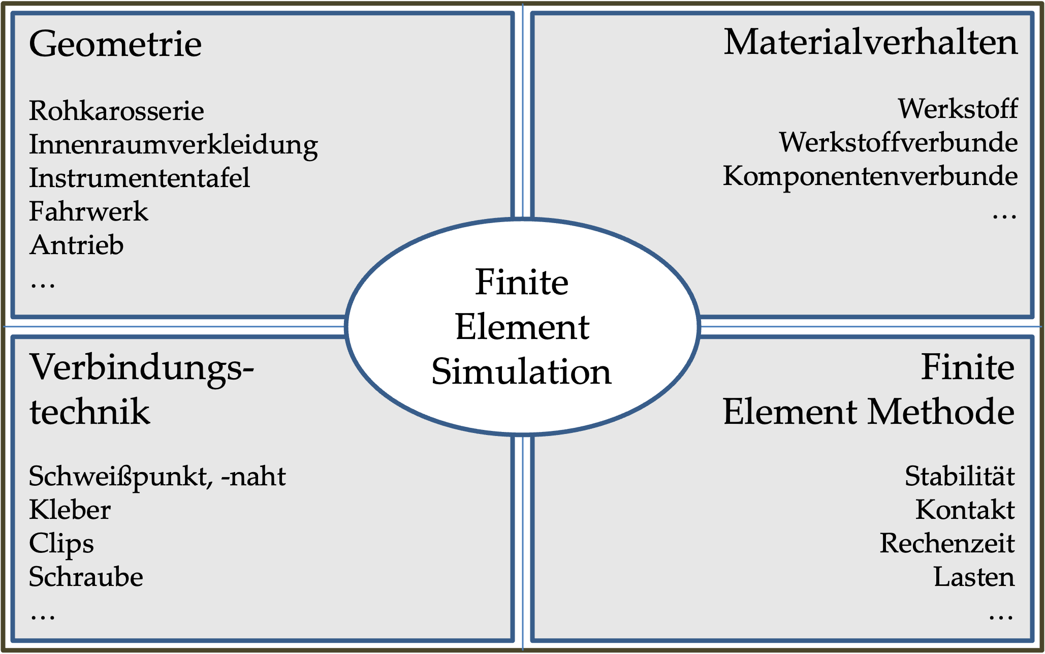
In an earlier publication [11], we explained that the quality and predictive power of a simulation depends on the quality of the mapping of geometry, material, connection technology and the algorithms of the finite element method.
We have borrowed the following image from this publication.
Depending on the qualitative and quantitative objectives of a simulation, quality should be checked and improved in individual or all areas.
The previous presentation contains examples and procedures for processing the areas.
We will use a simple shaft-hub connection as an example. Mapping the geometry and, if necessary, a connection technique is quite simple. In most cases, the dimensions (in the m range) and the necessary resolution (in the mm range) pose a challenge, especially for the hardware used. The material behavior is limited to the elasticity of a metal. The finite element simulation should provide results regarding the micro-movement between shaft and hub as well as the stresses in the area of the surface of the shaft, which are then used in a fatigue strength calculation. Although edge effects are initially excluded due to their singularity, fundamental investigations are required to “correctly” simulate the micromovements and stresses. However, a realistic simulation only allows a minimum element edge length of approx. 3 mm. The calculations were carried out with Abaqus/Standard [12].
First, a 3-dimensional test model is used.
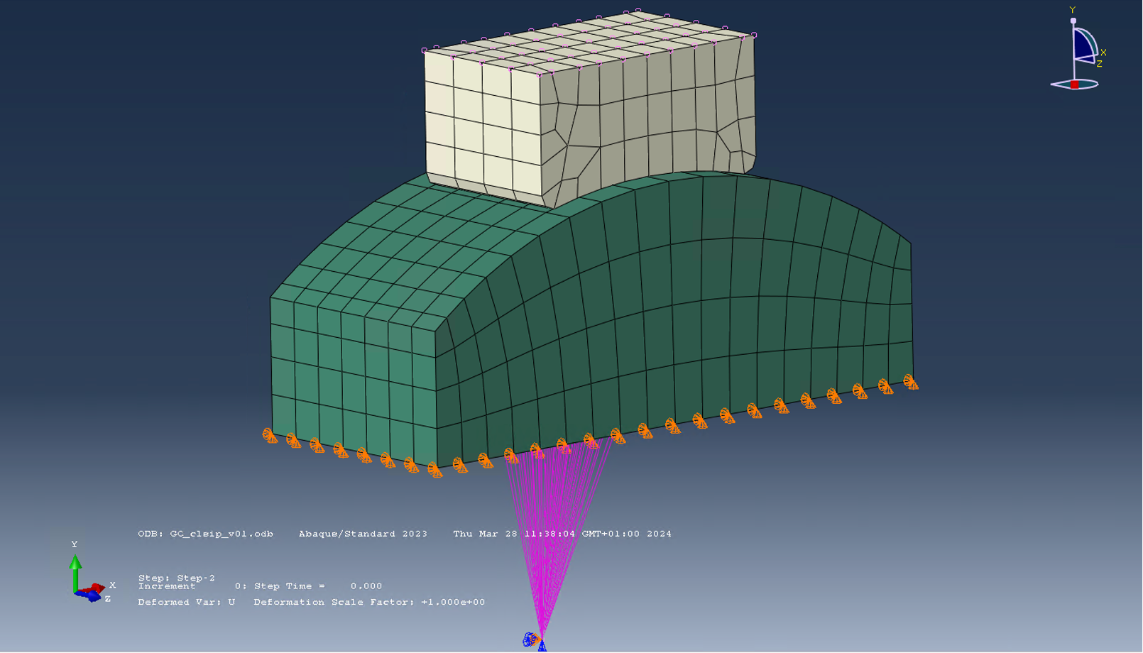
A component (impactor) is pressed against another component (block) by 0.03 mm (step 1) and then rotated by 0.01 degrees (step 2).
Both loads result in small relative displacements in the thousandths of a millimeter range.
The micromovements are to be evaluated at the contact surface.
The element type to be used, a fully integrated, linear 8-node solid element (C3D8I), has already been determined in preliminary investigations, see also [9].
The element edge lengths and the elastic slip of the penalty formulation for the friction were varied.
This is an elastic-ideal plastic description of the friction behavior in order to ensure stable convergence.
The elastic slip factor describes the elastic gradient (the smaller, the steeper).
This factor can be defined relative to the element edge length (Elastic Slip Tolerance) or as a dimension (Elastic Slip).
The following variants were calculated:
You can see that the components had to be partitioned in order to keep the model computable.
With v14, 128 GByte RAM was not enough, so that the simulation took an extremely long time.
The Abaqus variable CLSIPEQ is used here to determine the micromovement.
This represents the accumulated resulting movement in the contact plane.
If the default parameters are used, a comparison of the variants v11, v12, v13 and v14 shows a clear dependence of the result on the fineness of the mesh, see the following figure.
For the variants with 3 mm and 1 mm element edge length, the result still appears symmetrical.
The use of the default parameters therefore does not appear to be permissible for the detection of micromovements with a mesh with an edge length of 3 mm.
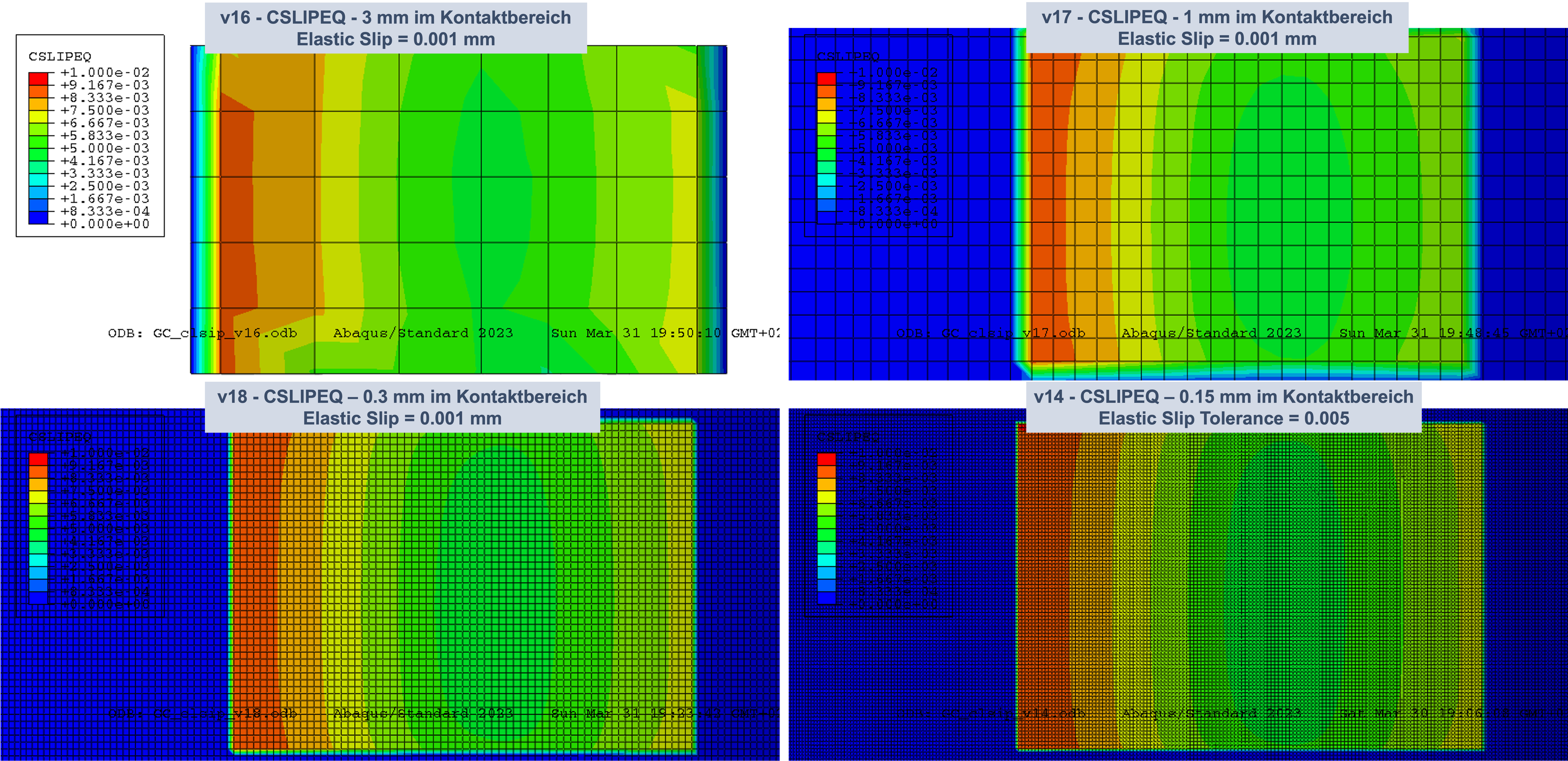
However, there is a simple solution that can be applied here by specifying a fixed elastic slip, as in this case, or a significantly smaller elastic slip tolerance.
Now the result for larger element edge lengths is much closer to the result with a very fine mesh, see the following image.
However, due to the significant differences in the element edge length, there are still differences which must be neglected.
Further literature can be found, for example, at [13].
The same model is also used to display the stresses as a function of the element edge length.
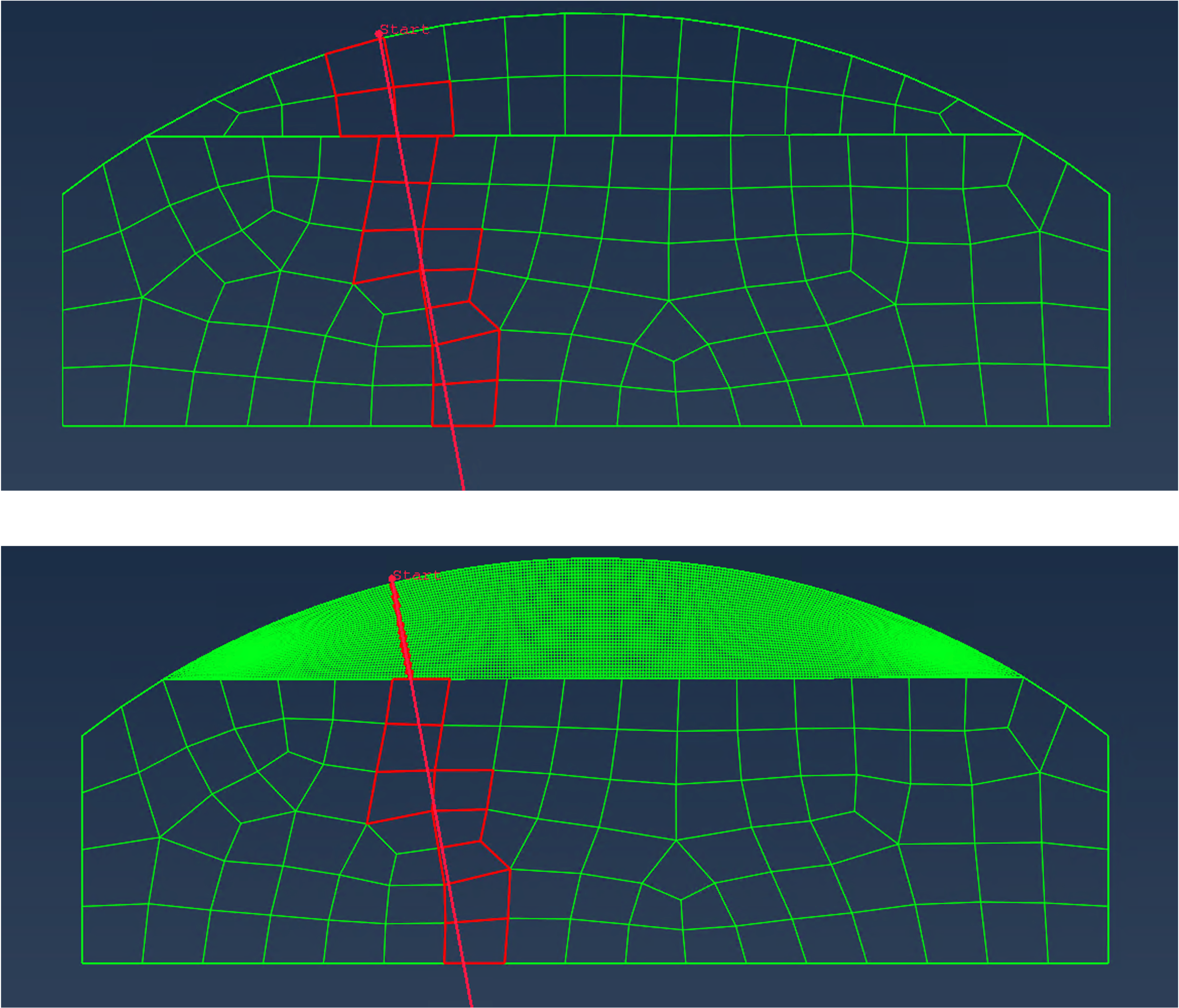
Abaqus makes it possible to determine the stresses along a path.
The representation of these paths in the following figure already shows that differences in the stresses in the block are to be expected.
However, a minimum element edge length of 3 mm is also required here for a simulation of the problem.
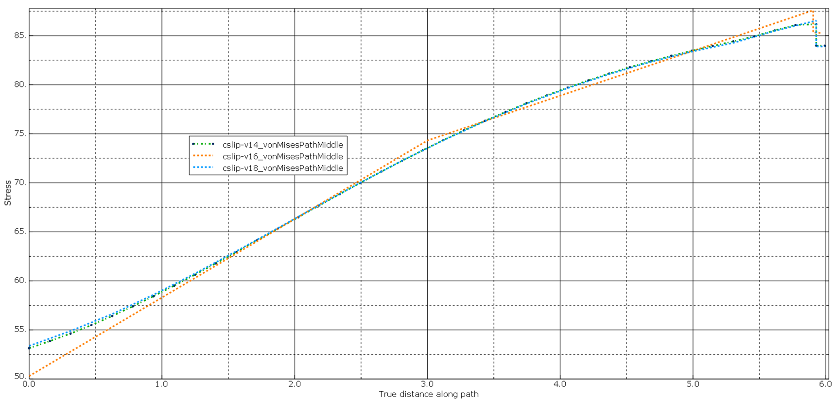
If we now look at the stresses along this path for the variants v14 (0.15 mm edge length), v16 (3 mm edge length) and v18 (0.3 mm edge length), the following stress curves are obtained along the path (starting at the surface), see the following figure.
The deviations here are small and can be neglected.
This small example shows that by correcting the default values for the contact, it is possible to make statements about micromovements and stresses even with a coarse mesh.
In this case, the correction of the default values also leads to only a slight change in the convergence behavior and thus the time required for the simulation.
When calculating shaft-hub connections, the bearing is usually represented in a simplified manner by coupling a part of the shaft in the bearing area with a central node.
The type of coupling and the correct choice of boundary conditions are then possible sources of error with considerable effects on the result.
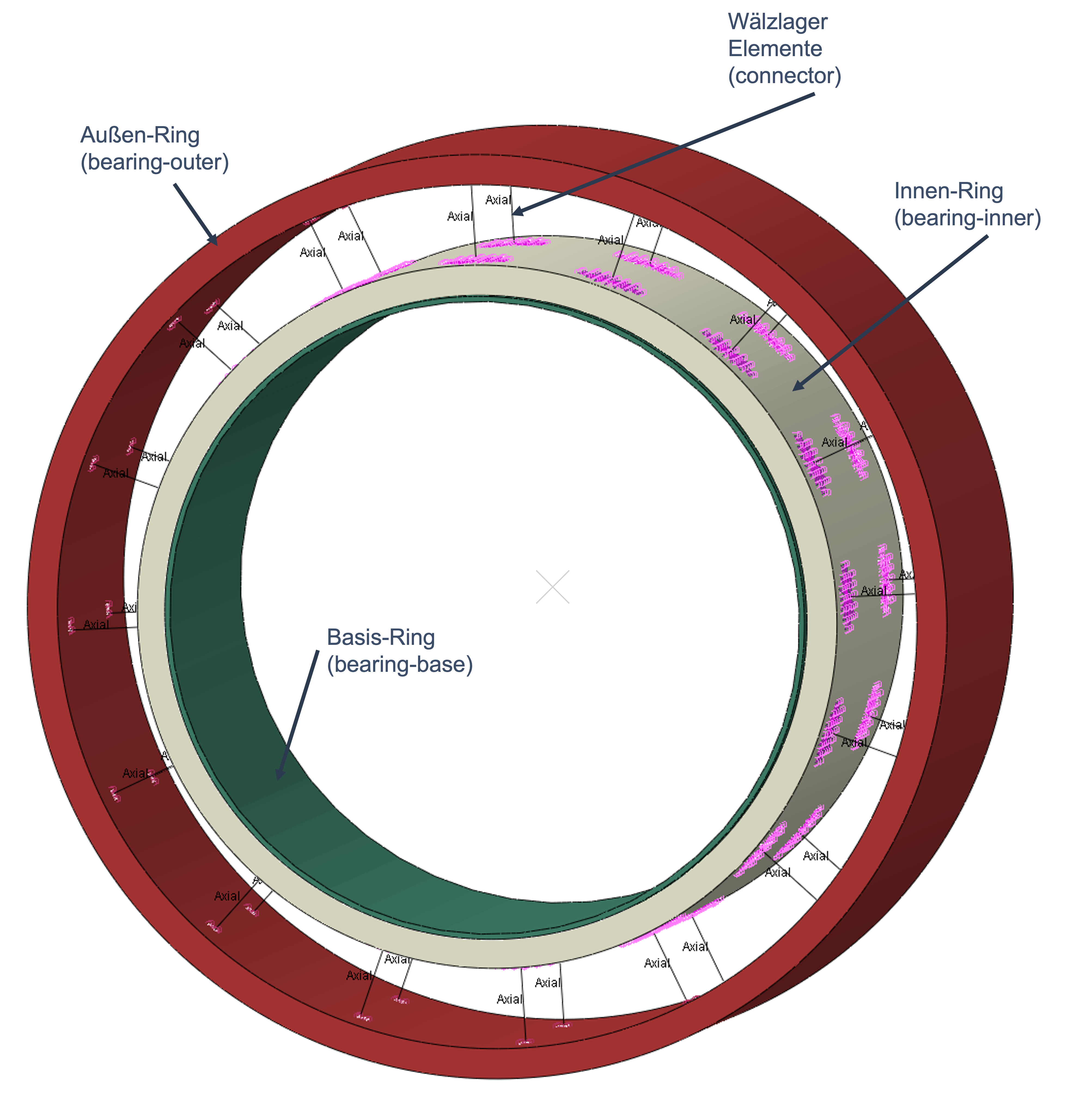
In a first approach, a different model was created for the bearing mapping, see the following figure.
However, such a model changes the convergence behavior and leads to an extension of the calculation.
The advantages of democratizing the simulation were described in an earlier article. In order to be able to utilize these advantages, the joint efforts of designers and calculation engineers are required.
The quality and predictive power of a simulation depend on the quality of the representation of geometry, material, connection technology and the algorithms of the finite element method.
It was shown that even for a supposedly simple problem such as a shaft-hub connection, preliminary investigations are necessary to define the necessary simulation parameters.
It was also shown that sources of error in a simplified approach must be identified and, if necessary, avoided by modifying the model.
Certainly applies:
- The simulation must offer added value in the product development process.
- The simulation should be capable of forecasting.
[1] “25th Bayreuth 3D Constructors’ Day on 11.09.2024”[Online] [Accessed: 19-Sep-2024].
[2] Brand, M., Baur, K., Brunner, S., and Gebhardt, C., 2020, Physik begreifen – besser konstruieren, Springer Berlin Heidelberg, Berlin, Heidelberg.
[3] Cline, G., 2017, THE BENEFITS OF SIMULATION-DRIVEN DESIGN, ABERDEEN GROUP.
[4] Karlsson, L., Pahkamaa, A., Karlberg, M., Löfstrand, M., Goldak, J., and Pavasson, J., 2011, “Mechanics of Materials and Structures: A Simulation-Driven Design Approach,” J. Mech. Mater. Struct, 6(1-4), pp. 277-301.
[5] Jackson, C., The Four Benefits of Simulation-Driven Design, Lifecycle Insights.
[6] “Structural Analysis For Fast Design Iterations | Altair SimSolid”[Online][Accessed: 28-Jun-2023].
[7] “Ansys Discovery | 3D Product Simulation Software”[Online] [Accessed: 28-Jun-2023].
[8] Popielas, F., 2022, “Introduction TO MODSIM.”
[9] systemworkx AG, “Home – PLM Blog & Knowledge Center – Simulation, etc.,” PLM Blog & Knowledge Center[Online][Accessed: 01-Oct-2023].
[10] Symington, I., 2020, “Designer Oriented Software – Is It Accurtae? Part 1,” NAFEMS Benchmark Magazine, (January 2020).
[11] Paßmann, Ralf, and Herrmann, Martin, “Finite Element Simulations in Der Praxis – Voraussetzungen Für Prognosefähige Berechnungen,” CAE-Forum Auf Der HMI 2015, Hannover.
[12] “Welcome to the SIMULIA User Assistance – SIMULIA User Assistance 2024”[Online][Accessed: 21-Sep-2024].
[13] Mäntylä, A., and Lönnqvist, C., 2009, “Fretting Simulation for Crankshaft-Counterweight Contact.”

