Extended Abstract K-Day 2024
Additive manufacturing or 3D printing of components has experienced a considerable upswing in the last ten years due to the development of printers and is now a standard manufacturing process.
The software manufacturers of finite element systems have invested heavily in making it possible to simulate additive manufacturing with minimal user effort.
A presentation last year, see also K-Day 2023, described digital process planning and the implementation of simulation on the 3DEXPERIENCE platform from Dassault Systèmes.
The focus of this article is on the SLS process (Selective Laser Sintering).
The process is similar to the laser powder bed process in the last article.
For plastic materials in particular, however, the non-exposed powder has a supporting effect.
This means that no support structures are required for plastics.
The necessary imaging of the powder is not directly provided for in 3DEXPERIENCE.
This article describes a self-created, modified workflow using an example.
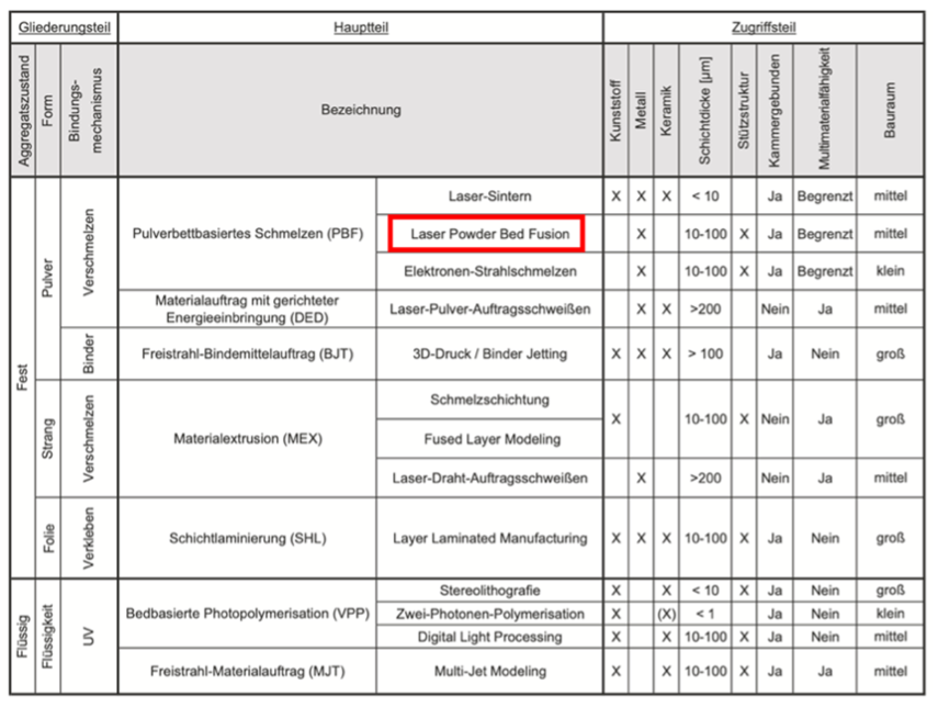
An overview of the various additive manufacturing processes can be found in [1] and begins with the aggregate state, see the following figure.
Laser sintering, like the laser powder bed process for metals, is a PBF process.
In the contribution to K-Tag 2023, [2], we limited ourselves to the laser powder bed process.
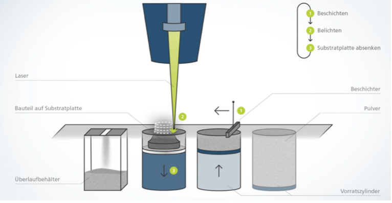
Here, a thin layer of metal powder is spread on a table using a coater, see the following image from [3], and then exposed by a laser.
The table is then lowered and another layer of powder is applied, which is exposed again.
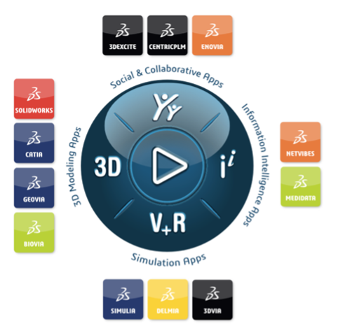
With 3DEXPERIENCE, Dassault Systèmes provides a platform for digital product development, see [4].
A key element is the compass, see image.
The various brands arranged around the compass provide apps that are assigned to user roles.
The DELMIA and SIMULIA brands from the quadrant for simulation apps are essential for the applications shown here.
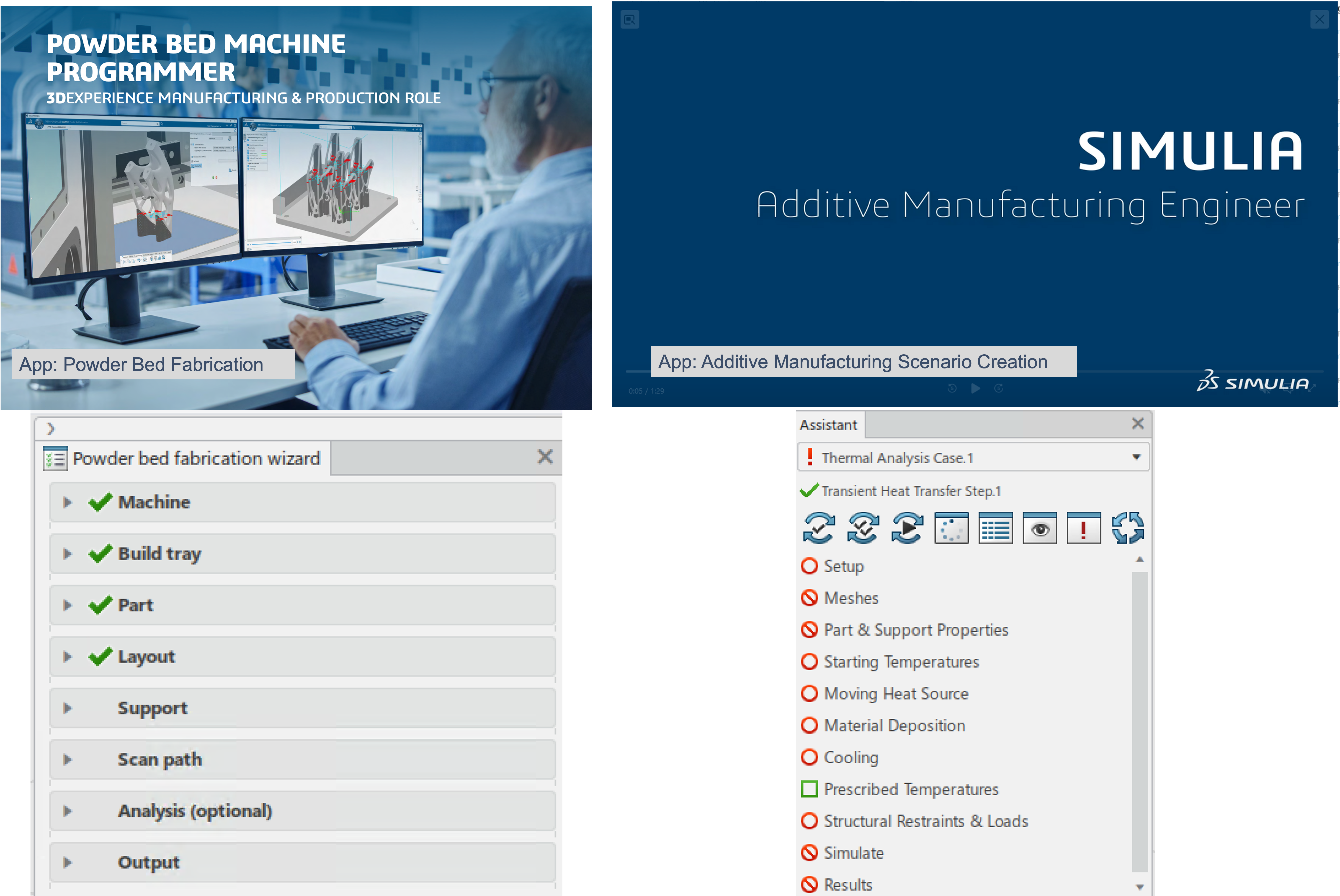
Here, the ‘Powder Bed Machine Programmer’ role with the ‘Powder Bed Fabrication’ app is used to set up the process and the ‘Additive Manufacturing Analysis Engineer’ role with the ‘Additive Manufacturing Scenario Creation’ app is used for the simulation, see the following image.
Guided processing sequences are a key feature of the 3DEXPERIENCE platform.
These have the great advantage of a controlled and structured approach.
However, the platform allows manual intervention beyond this guidance at any time.
The presentation showed how the process preparation can be completed and a simulation of temperature, stresses and distortion can be carried out by working through the points of the respective wizard.
The transfer of essential information such as the component arrangement or the laser scan path is largely automatic.
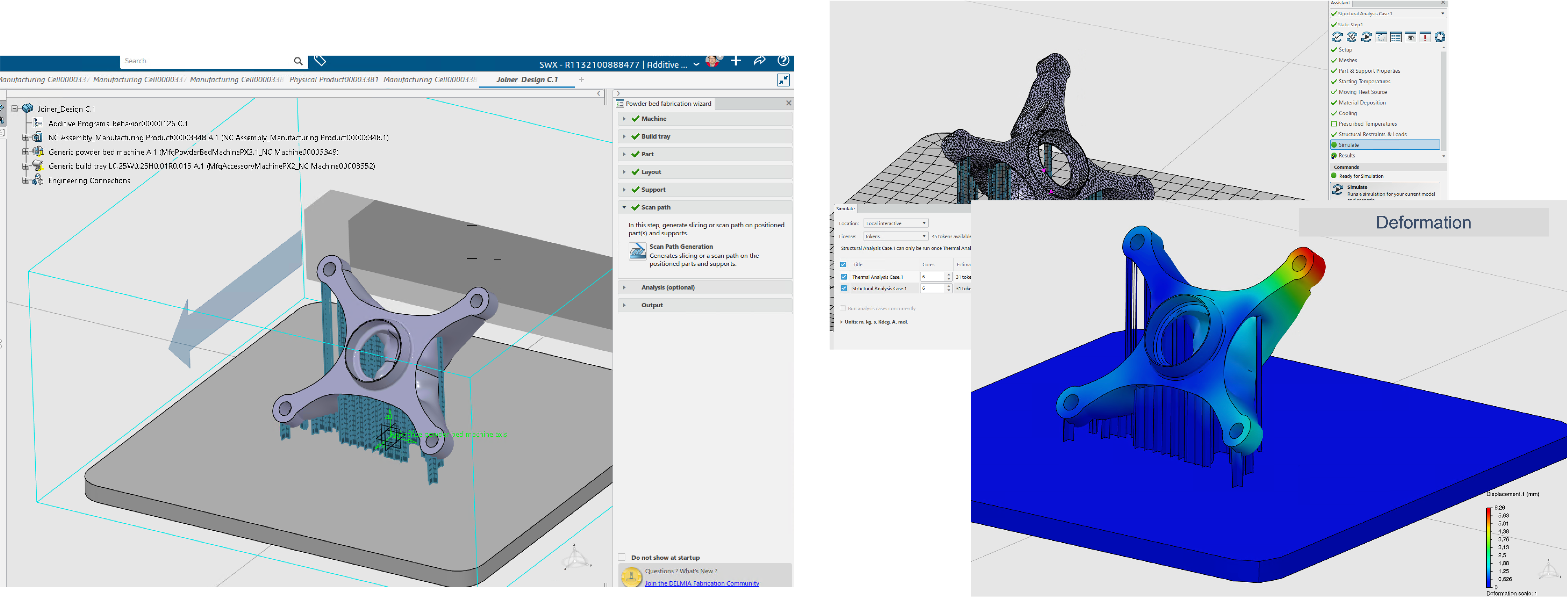
The following image on the left shows the result of the process preparation with the positioned component and the necessary support structures.
The right-hand side shows the result of the simulation of the deformation of the component after completion of production.
Using 3DEXPERIENCE and the aforementioned roles and apps, it is very easy to define the additive manufacturing process and analyze it using simulation.
The example of the Powder Bed process of metals used in the contribution to K-Day 2023 demonstrates this.
Further explanations of the literature and the consideration of the process can be found in this presentation.
This article will take a closer look at the SLS process for manufacturing plastic components.
The process is very similar to the additive manufacturing process for metals described in the review.
The main difference is the unexposed powder.
This powder is so compact that it supports the components and therefore no support structures are necessary.
In this case, heat is dissipated only via the powder, which dissipates the heat very slowly.
The compactness of the powder can be clearly seen in a video on the 3DSystems website [5].
The following image shows a few excerpts from this video.
At present, 3DEXPERIENCE is not designed to display the powder.
There is also no need to display the powder in the process preparation.
A particular advantage of the integration of process preparation and simulation on the 3DEXPERIENCE platform is the automatic transfer of the layer formation in the simulation.
The latter would otherwise have to be defined by the user, but is actually a machine parameter.
Accordingly, a work process was set up here which already takes the powder into account during process preparation.
However, another approach would also be conceivable.
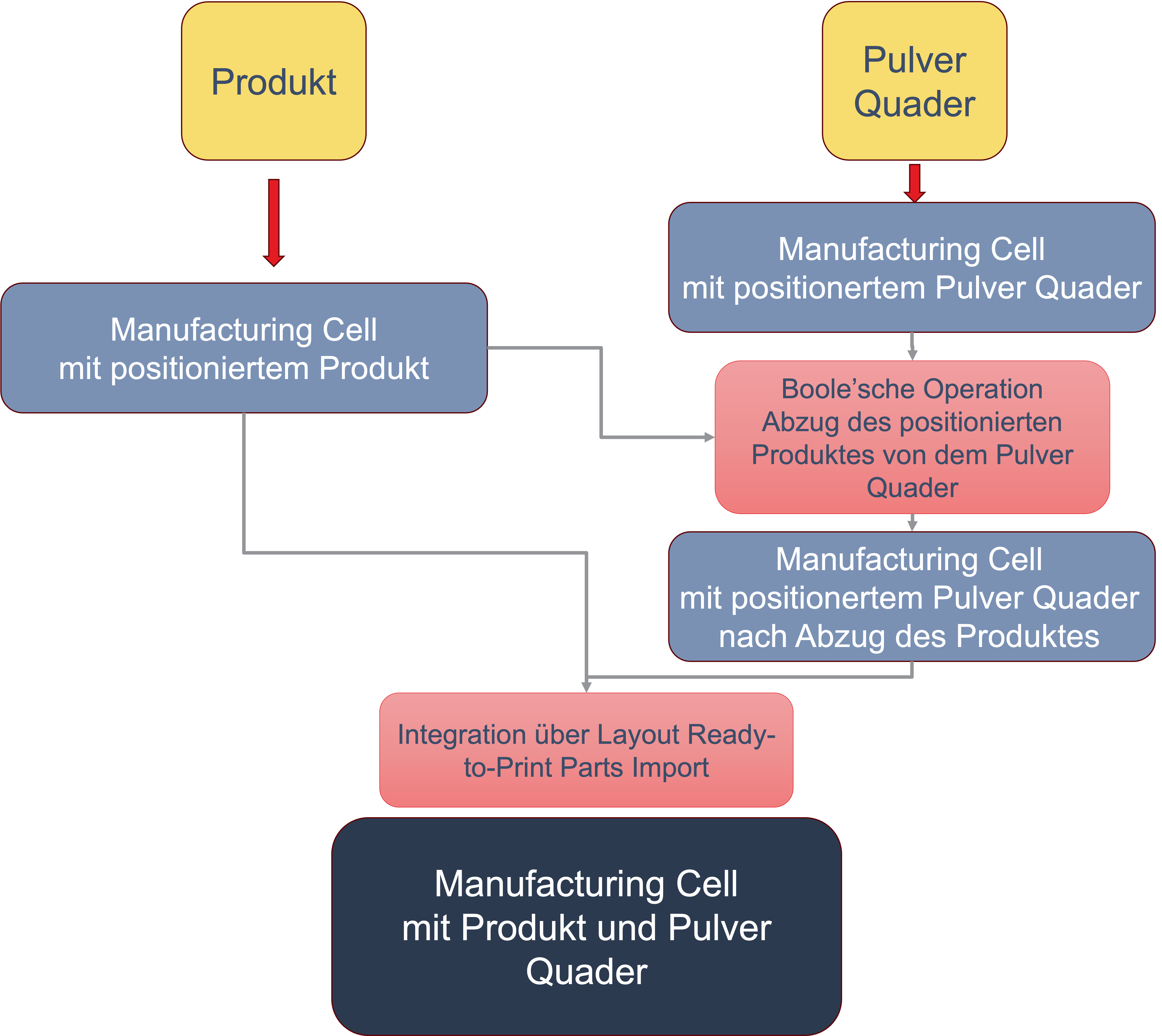
The process set up is shown in the following picture.
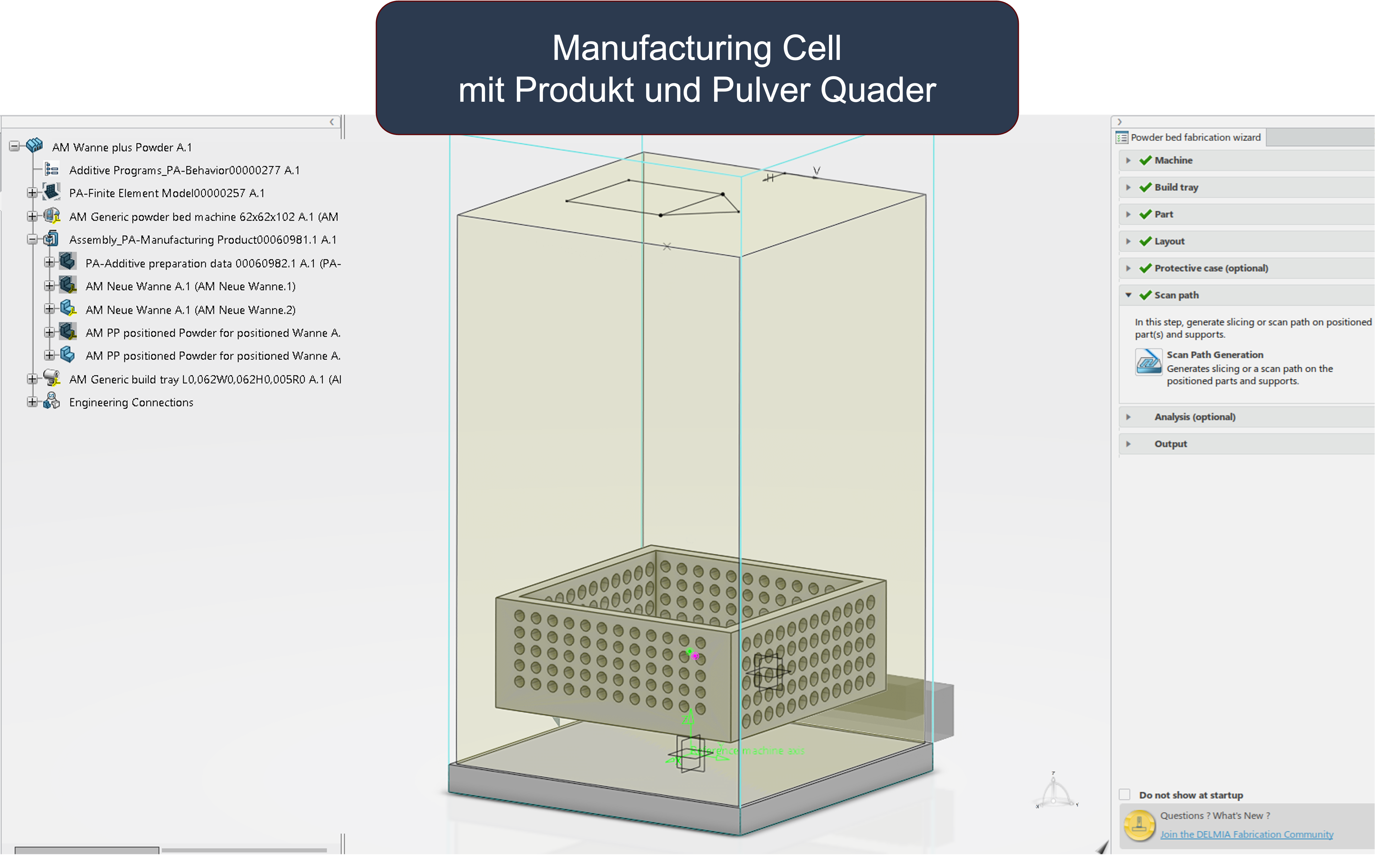
The process starts with the CAD models of the product and powder cuboid and the selection of a specific machine with table.
The machine and table are used repeatedly.
The parameters for powder application and exposure are linked to the machine.
These are used in the workflow every time a manufacturing cell is set up.
The parameters for the layout should also always be defined in advance.
The powder cuboid and product are each positioned in a Manufacturing Cell.
The powder is then exported and reduced by the product using a Boolean operation.
The reduced powder cuboid is then positioned again on the table.
This means that 2 manufacturing cells are available.
A new manufacturing cell is now created.
Here you skip the working point for importing the parts (components) and select the import of already positioned components in the layout.
Then define the scan path for the powder cuboid and product.
In principle, different lasers can be used.
However, it should be noted here that the depicted powder cuboid is not necessary for the machine control.
The manufacturing cell of the product created first could be used for machine control.
In principle, several product components can be used.
The workflow was carried out using an example.
The product has been created in such a way that it contains both small and large areas.
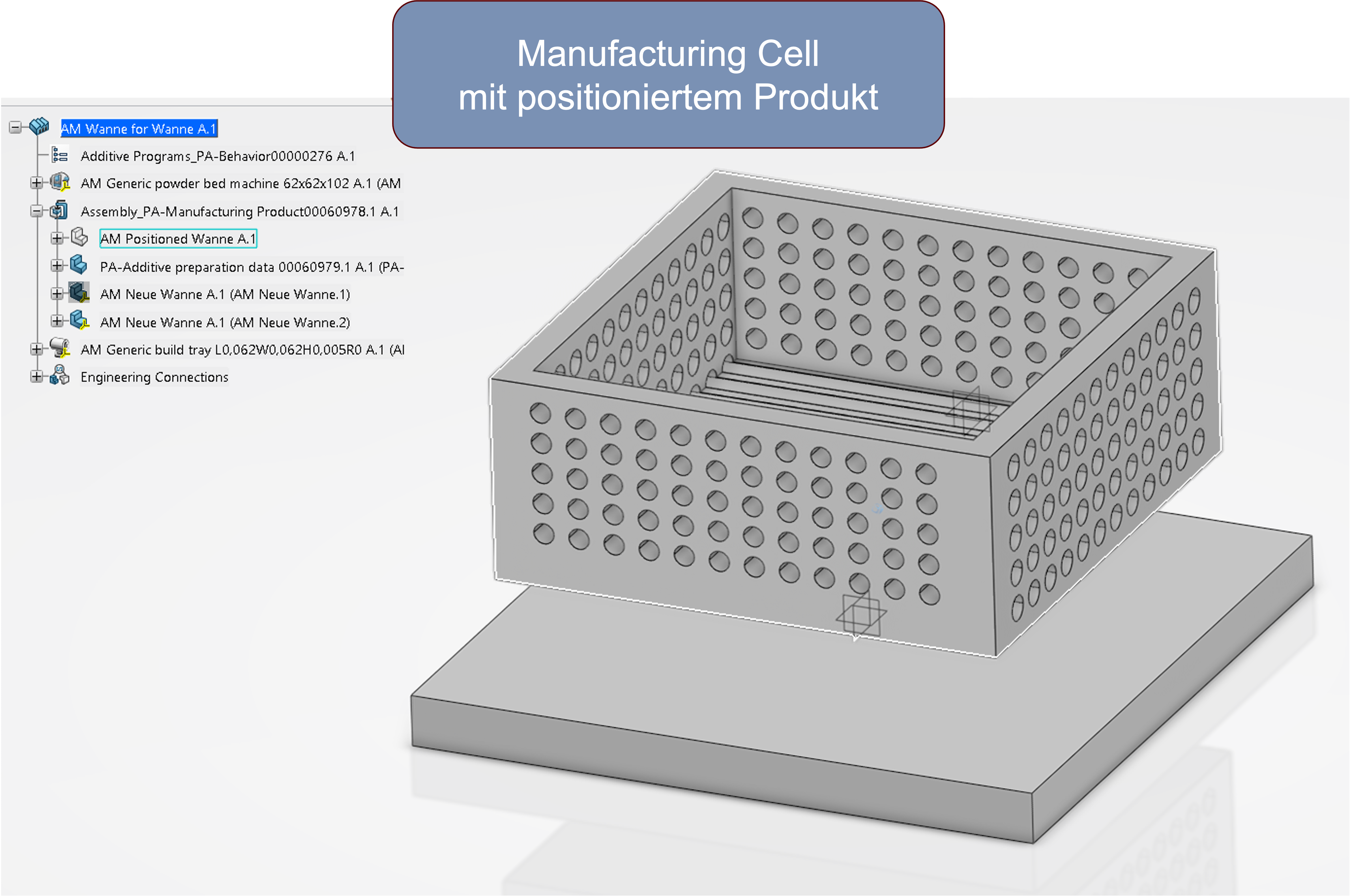
The following image shows the product positioned in a manufacturing cell.
This is a box with drilled side walls.
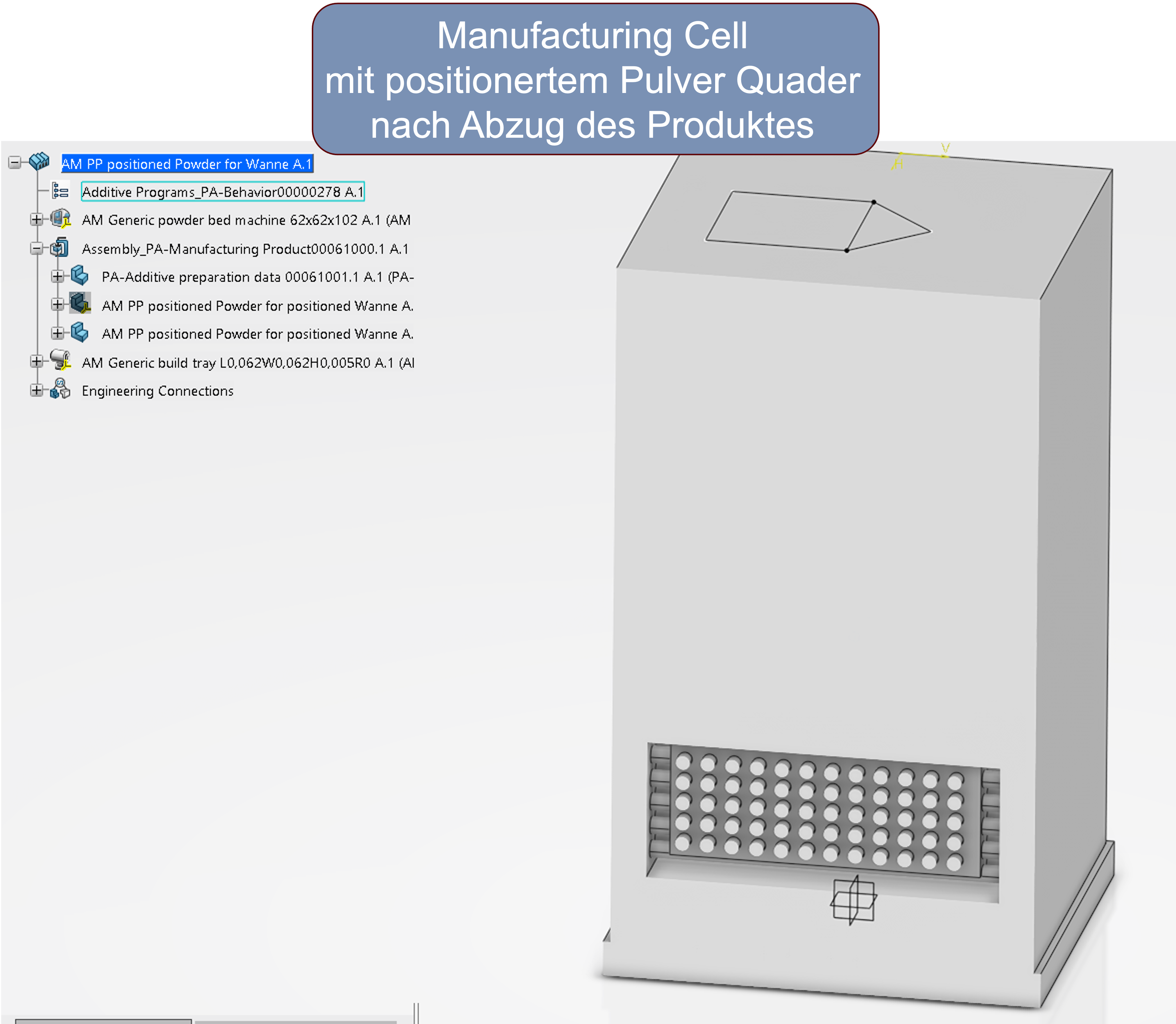
A manufacturing cell was set up for the powder cuboid.
The product was removed from the positioned cuboid using a Boolean operation and a manufacturing cell was set up again, see the following image.
After importing the product and powder cuboid as ready-to-print parts, the arrangement is complete, see the following image.
The laser path is now created.
As described in the article on K-Day 2023, you can switch to simulation simply by switching to the 3DEXPERIENCE app.
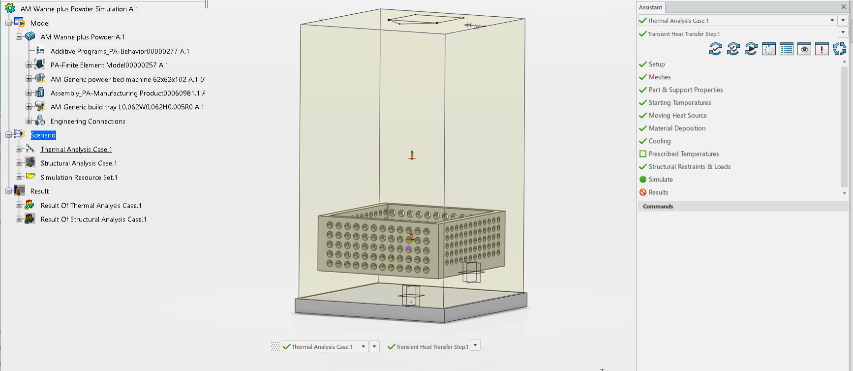
The procedure for the simulation is essentially based on the procedure from the K-Day 2023 article and follows the specifications of the wizard, see the following image.
One advantage of the app for creating the simulation is the distinction between ‘Moving Heat Source’ and ‘Material Deposition’.
This means that a heat source is only assigned to the product, while the deposition of the material (material deposition) is assigned to the product and powder cuboid.
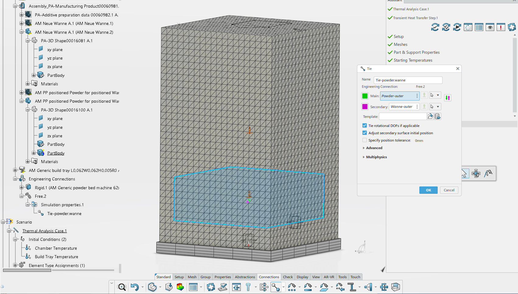
In contrast to the wizard, a connection must be established between the powder cuboid and the product for the simulation of temperature and structural mechanics.
As can be clearly seen in the 3DSystems image, a solid connection is created between the powder and the component.
Accordingly, a TIE connection is defined, see the following image.
The simulation is then carried out.
The following image shows the temperature distribution for the pressure of the soil in the left partial image and for the pressure of a series of boreholes in the right partial image.
In our contribution to K-Day 2023, we showed how the process and simulation of additive manufacturing are defined in the 3DEXPERIENCE platform using the example of metal powder printing.
Both the definition of the process and the setup of the simulation are guided by a wizard, which significantly reduces the effort and complexity of the task.
The sequential thermal-mechanical coupled analysis was demonstrated.
In this article, we have now created an example of selective laser sintering (SLS) of plastics.
Since it is necessary to take the powder into account in the simulation, a necessary workflow was defined.
The workflow is currently still quite complex, but it should be possible to shorten it through automation.
In part, this text and illustrations shown are based on research of evaluated literature. If this is the case, the sources are marked in the text by a number, e.g. [2], and the source is listed here. In part, however, the sources listed here should simply be understood as recommendations for further reading.
[1] Lachmayer, R., Ehlers, T., and Lippert, R. B., 2022, Entwicklungsmethodik für die Additive Fertigung, Springer Berlin Heidelberg, Berlin, Heidelberg.
[2] “25th Bayreuth 3D Constructors’ Day on 11.09.2024”[Online] [Accessed: 19-Sep-2024].
[3] “Like a phoenix from the ashes”[Online] [Accessed: 29-Aug-2023].
[4] “We Are the 3DEXPERIENCE Company | Dassault Systèmes”[Online] Accessed: 20-Jul-2023].
[5] “3D Printers, Software, Manufacturing & Digital Healthcare | 3D Systems”[Online] [Accessed: 19-Sep-2024].
